
Sunlight automatic tracking photothermal catalysis-membrane separation reaction system

A photothermal catalysis, automatic tracking technology, applied in chemical instruments and methods, chemical/physical processes, light water/sewage treatment, etc. Utilization and mass transfer efficiency, meeting light and thermal energy requirements, and maximizing light energy utilization

Active Publication Date: 2013-01-16
TIANJIN URBAN CONSTR COLLEGE
View PDF6 Cites 8 Cited by
  • Summary
  • Abstract
  • Description
  • Claims
  • Application Information

AI Technical Summary

Problems solved by technology

Due to the low flow rate, small Reynolds number, and laminar flow state of the fixed photocatalytic reactor, there are disadvantages such as mass transfer limitation and high energy consumption; at the same time, the reactor is not closed, and the catalyst is greatly affected by the surrounding environment , can easily cause catalyst poisoning
The packed bed photocatalytic reactor is filled with TiO 2 Particle or surface coated with TiO 2 The silica gel, alumina and quartz sand of the membrane have high mass transfer capacity; however, the collision between particles will cause the membrane to fall off, so it is not necessary to use long-term operation
The mixed solution of catalyst particles and pollutants in the suspension photocatalytic reactor is in a turbulent state, without mass transfer restrictions; at the same time, the reactor is in a closed state, and there is no problem of evaporation of volatile pollutants; however, there are catalyst separation and recovery, repeated The problem of utilization, therefore, how to realize the separation, recovery and recycling of the catalyst is the main problem faced by the suspension photocatalytic reactor

Method used

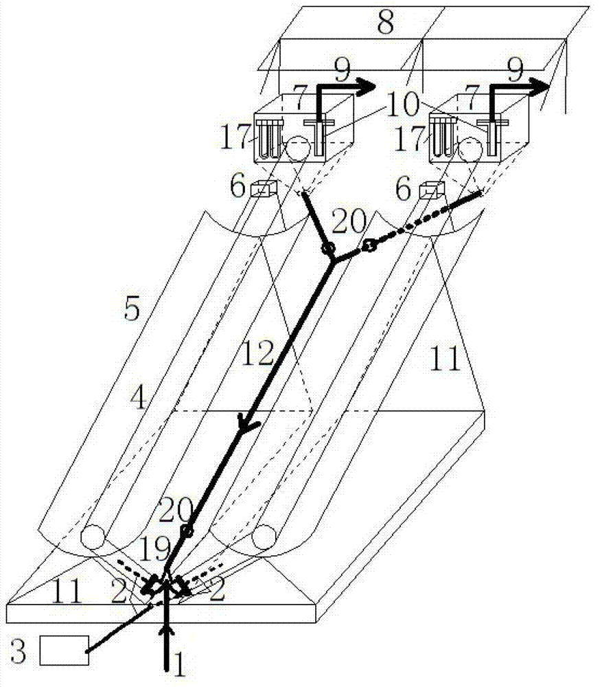
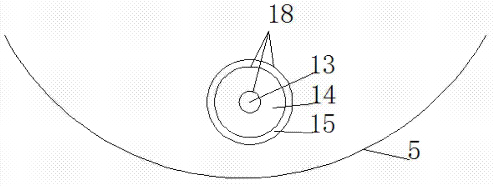
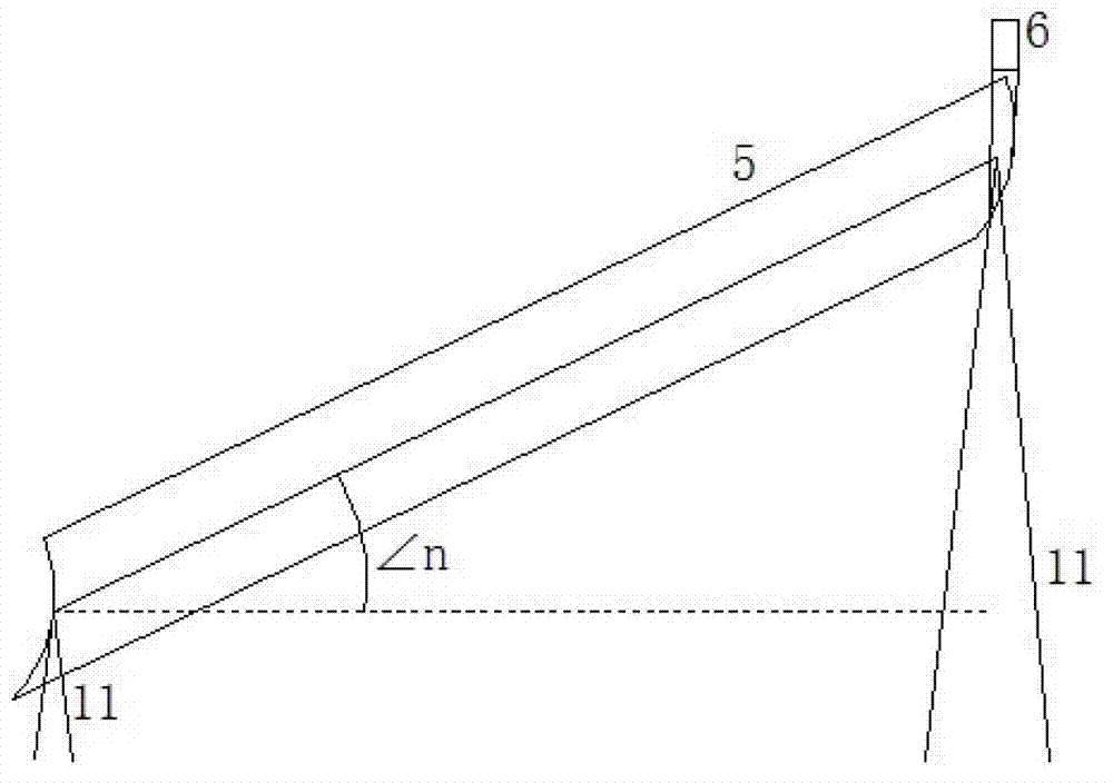

Image

  • Sunlight automatic tracking photothermal catalysis-membrane separation reaction system
  • Sunlight automatic tracking photothermal catalysis-membrane separation reaction system
  • Sunlight automatic tracking photothermal catalysis-membrane separation reaction system

Examples


Embodiment Construction

[0028] The photothermal catalysis-membrane separation reaction system with solar automatic tracking function of the present invention will be described in detail below in conjunction with the accompanying drawings.

[0029] The structure of the sunlight automatic tracking photothermal catalysis-membrane separation reaction system of the present invention is: the system includes a photothermal catalysis reaction zone, a membrane separation zone, a system control zone, and a solar power generation zone; The catalytic reaction tube is connected to the gas-liquid separation water tank in the membrane separation area, and the TiO after being separated by the membrane separation area 2The catalyst mixture returns to the photothermal catalytic reaction area through the circulation pipe, thus forming a circular reaction system. The system control area controls the working state of the system through the adjustment device of the system control panel, and the solar power generation area ...


PUM


Abstract

The invention provides a sunlight automatic tracking photothermal catalysis-membrane separation reaction system, and aims at providing a high-efficient photothermal catalytic reaction system, which comprises a photothermal catalytic reaction zone, a membrane separation zone, a sunlight automatic tracker, a system control zone, and a solar power generation zone. A TiO2 catalyst is well mixed with pollutants in an aeration mixing driving mode so as to promote the circulation flow of the mixed solution for a photothermal catalytic reaction. The system can perform all-weather tracking of sunlight by driving of the sunlight automatic tracker, and has quite high efficiency for solar energy utilization and mass transfer efficiency; the arrangement of the sunlight automatic tracker greatly improves the efficiency for pollutant removal by the photothermal catalytic reaction, and thus maximizes the efficiency for solar energy utilization; the electric energy provided by the solar power generation zone can meet the electric quantity required by the whole system, and thus the system gets rid of the restriction of external power supply, and truly realizes high efficiency, energy saving, and self-sufficiency.

Description

technical field [0001] The invention relates to a photothermal catalysis reaction system, which is a sunlight automatic tracking photothermal catalysis-membrane separation reaction system. The invention is a photocatalytic oxidation wastewater treatment device which is not affected by the weather. The device can be applied not only to the pretreatment or advanced treatment of toxic, harmful and refractory organic wastewater, but also to the advanced treatment of slightly polluted drinking water. Background technique [0002] Energy shortage is a very serious problem facing the world. As a clean and pollution-free new energy source, solar energy has a very broad development prospect. With the research on the large-scale development and utilization of solar energy, it is found that the daylighting rate and The photoelectric and photothermal conversion rates are low; the use of solar automatic trackers can make the solar lighting panels always perpendicular to the sunlight, mai...

Claims


Application Information

Patent Timeline
Patent Type & Authority Applications(China)
IPC IPC(8): B01J8/22C02F1/00C02F1/30C02F1/32C02F1/44
CPCY02W10/37
Inventor 费学宁解立平姜远光董业硕刘玉茹
Owner TIANJIN URBAN CONSTR COLLEGE
Learn More