
Coal gasification method

A gas and pulverized coal technology, applied in the field of coal gasification, can solve the problems of slow heat transfer rate and long duration

Inactive Publication Date: 2013-01-23
赵庆晨
View PDF4 Cites 3 Cited by
  • Summary
  • Abstract
  • Description
  • Claims
  • Application Information

AI Technical Summary

Problems solved by technology

The benefit of this method is that the superficial flow rate of the gasification agent can be further increased; but the disadvantage is that although the use of carrier gas facilitates the feeding of pulverized coal and facilitates the improvement of the mixing efficiency of pulverized coal and gasification agent, the heat from high temperature gasification It takes a long time for the agent to transfer to the pulverized coal itself. The high-temperature gasification agent first needs to preheat the carrier gas, and then the heat is transferred from the main body of the gas phase to the solid coal powder, and the heat transfer rate is relatively slow.

Method used


Image

  • Coal gasification method
  • Coal gasification method
  • Coal gasification method

Examples


Embodiment 1-5

[0041] use figure 2 In the manner described in , the lignite pulverized coal produced in Inner Mongolia that is dried and ground to a particle size of about 1mm is loaded into the pulverized coal silo, and the pulverized coal is directly discharged perpendicular to the first flow channel through the star discharge valve. was added to the combustion flue gas from an oil burner flowing at the temperatures and superficial velocities described in the table below, without using any carrier gas to transport the pulverized coal. The first flow channel is a section of horizontal pipeline, made of 310S steel, lined with mullite refractory layer, the length of the first flow channel is 6 meters, and a high-temperature cyclone separator is installed at the end of the pipeline to separate the semi-coke and the first gas product Separate and immediately analyze the volatile content in the semi-coke. The analysis method is according to GB / T212-2008, and the results are also listed in Table...

Embodiment 6-8

[0054] use Figure 4 The gasification device shown in series with the first flow channel and the second flow channel is used for gasification experiments, and the high-temperature cyclone separator is placed at the end of the second flow channel, wherein the cross-sectional area of ​​the second flow channel is the first flow channel The cross-sectional area is 25 times, and the experimental parameters are shown in Table 4. Wherein the second gas stream is oxygen, and its temperature after mixing with the first product stream is controlled at 800°C. A high temperature cyclone separates the ash from the second gaseous product. The residual carbon content in the ash was measured and found to be substantially less than 4%, indicating that the total carbon conversion rate can reach more than 96%. Of course, if the length of the second flow channel is further extended or the feed amount of O2 is increased, the total carbon conversion rate will be further improved, even close to 10...


PUM


Abstract

The invention discloses a coal gasification method which comprises the step of enabling coal powder to contact a first gas flow flowing in a first runner to obtain a first product flow containing a first gas product and semi-coke, wherein the temperature of the first gas flow is T1 which is at least 900 DEG C, when the contact occurs, the difference of superficial velocities of the first gas flow and the coal powder on the macro flowing direction of the first gas flow is more than 10m / s, the first gas flow can be flame, combusting smoke, water vapor, air, oxygen, plasma, inert gas or a mixture of flame, combusting smoke, water vapor, air, oxygen, plasma and inert gas, and the first gas product comprises synthesis gas and / or acetylene and / or methane.

Description

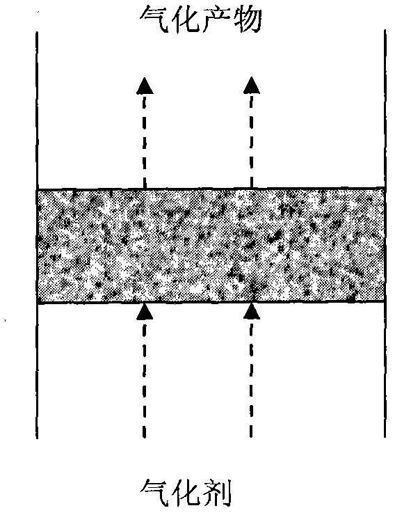
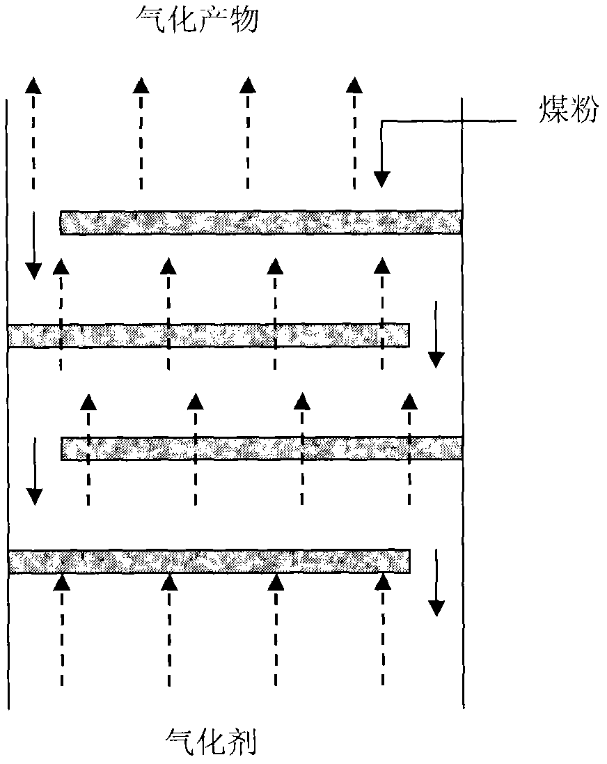
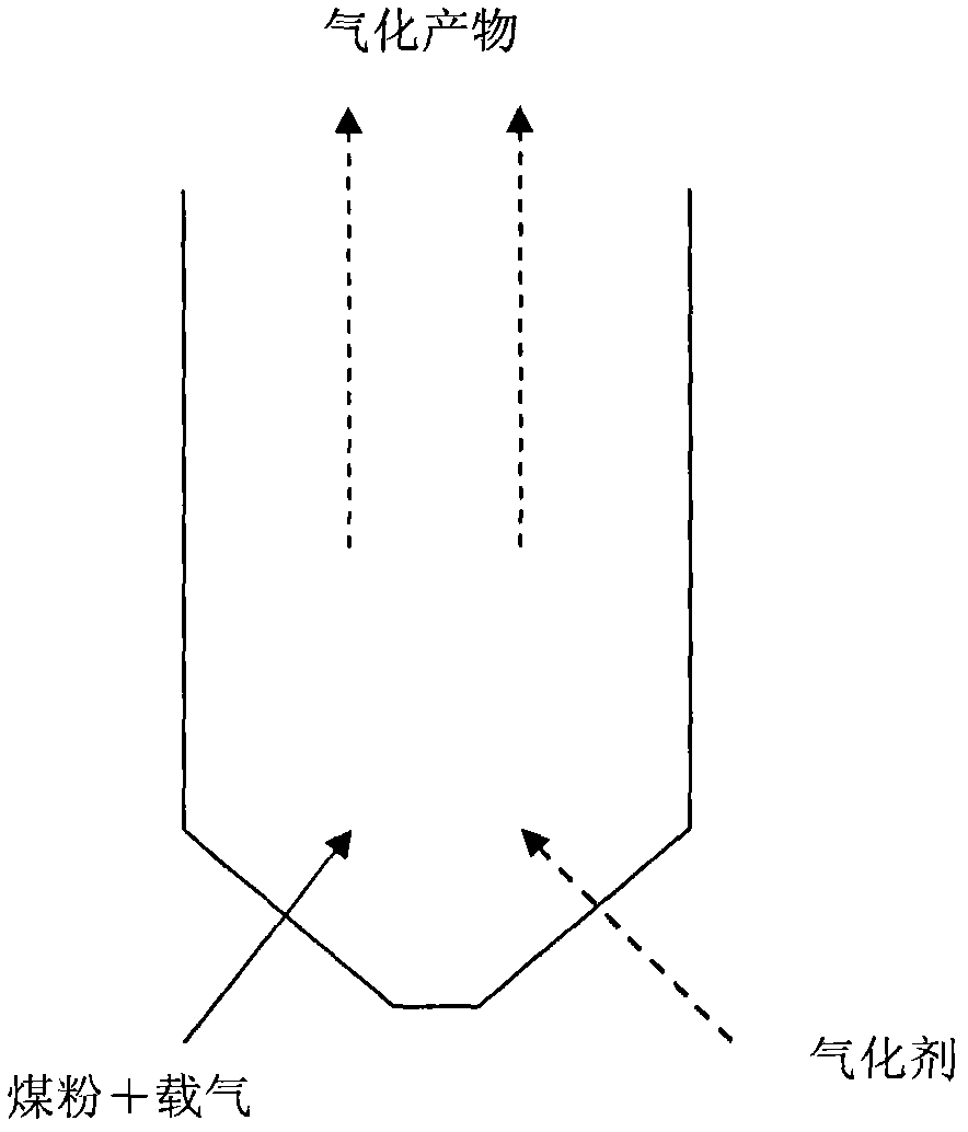
Background technique [0001] The gasification of coal to produce gaseous fuel or industrial raw material gas is of great significance for the deep processing of coal and clean energy technology. There have been many literatures discussing the technology of coal gasification to produce syngas or natural gas or acetylene . The literature on this subject is overwhelming. [0002] Generally, gasification is performed by contacting pulverized coal with a gasification agent. Among the currently known coal gasification technologies, the relatively mature ones include crushed coal fixed bed gasification technology and pulverized coal pressurized fluidized bed technology. In these prior art gasification technologies, the contact modes of coal and gasification agent are generally as follows: [0003] a. The gasification agent flows through the coal particle layer in the fixed bed to realize the contact and gasification of the two, wherein the coal is in a static state relative to the ...

Claims


Application Information

Patent Timeline
IPC IPC(8): C10J3/46C10J3/60C10J3/66
Inventor 陈莹
Owner 赵庆晨
Learn More