Self-lubricating twist drill and machining method thereof

A twist drill and self-lubricating technology, applied in twist drills, metal processing equipment, manufacturing tools, etc., can solve problems such as difficult to achieve expected results, rapid tool wear, tool breakage, etc., to improve the quality of the machined surface, reduce friction and cutting. Heat, reducing tool wear effect

Inactive Publication Date: 2013-02-13
XIAN TECHNOLOGICAL UNIV
View PDF5 Cites 4 Cited by
  • Summary
  • Abstract
  • Description
  • Claims
  • Application Information

AI Technical Summary

Problems solved by technology

[0005] On the one hand, in order to improve the performance of twist drills adapting to different materials, on the basis of designing reasonable cutting parameters and chip flute structure dimensions, the undercut phenomenon that occurs during processing, that is, the axial section of the rotary surface of the slot milling cutter The shape of the chip flute is different from the truncated shape of the chip flute in any section of the workpiece. To accurately process the correct spiral flute shape, it is necessary to fit the shape of the milling cutter edge. Therefore, the existing structure has processing difficulties and it is difficult to achieve the expected effect. The problem
[0006] On the other hand, in dry cutting conditions, friction and cutting heat will cause rapid wear of the tool, and even cause the tool to break. In order to improve the cutting conditions, in most cases, it is necessary to use coolant to solve this problem, but the coolant The use not only increases the cost, but also causes environmental pollution

Method used


Image

  • Self-lubricating twist drill and machining method thereof
  • Self-lubricating twist drill and machining method thereof
  • Self-lubricating twist drill and machining method thereof

Examples


Embodiment

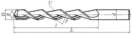
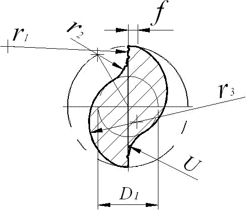
[0075] φ Nominal outer diameter of 25 self-lubricating twist drills D =25mm, flute helix angle β =38°; drill core diameter D 1 Take 0.5 D , edge width B=2.5mm, the processing material is No. 45 steel. According to the structural size of the self-lubricating twist drill, calculate the center coordinates and radii of the three tangent arcs (the other three tangent arcs are symmetrical to the drill center).

[0076]

[0077] cutting arc ( r 1 ) center coordinates ( x 1 , y 1 )for:

[0078]

[0079] Curl Arc ( r 2 )for:

[0080]

[0081] Chipping arc radius ( r 2 ) center coordinates ( x 2 , y 2 )for:

[0082]

[0083] Curl Arc ( r 2 ) and tooth back arc ( r 3 ) point of tangency coordinates ( x 4 , y 4 )for:

[0084]

[0085] Tooth back arc radius ( r 3 ) center coordinates ( x 3 , y 3 )for:

[0086]

[0087] Tooth back arc ( r 3 ) and the nominal diameter of the self-lubricating twist drill ( D ) intersection point ...


PUM


Abstract

The invention relates to a self-lubricating twist drill and a machining method of the self-lubricating twist drill. The invention provides the twist drill with a lubricating groove, which has the advantages of high strength, large scrap containing space, primary machining formation of the groove and a back, and capability of being designed according to different machining materials. Particularly, in a deep hole machining process, self-lubricating cutting is carried out without the cooling and lubricating effect of cutting liquid, so that the cutting friction is reduced and the effective scrap removing and scrap cutting are carried out. The technical scheme is as follows: an axial section of the self-lubricating twist drill is formed by a cutting circular arc, a scrap coiling circular arc and a tooth back circular arc; the structural size comprises an outer diameter D, a drilling core diameter D1, a blade belt f, a cutting circular arc r1, the scrap coiling circular arc r2, the tooth back circular arc r3, and the lubricating groove U on the cutting circular arc r1; the cutting circular arc r1 is smoothly tangent with the scrap coiling circular arc r2; the scrap coiling circular arc r2 is smoothly tangent with the tooth back circular arc r3; the scrap coiling circular arc r2 and the tooth back circular arc r3 are tangent with the drilling core diameter D1; and the cutting circular arc is provided with no less than one lubricating groove.

Description

technical field [0001] The invention relates to the field of design and manufacture of cutting tools in metal cutting, in particular to a self-lubricating twist drill and a processing method thereof. Background technique [0002] When processing different metal materials, due to the different workpiece materials, the degree of deformation of the chips during the cutting process is also different, so the types of chips produced are also diverse. According to the shape and hardness of different materials, the cutting strength of the cutting tool, The chip space of the flute shape, the size of the margin, the chip volume and the chip breaking condition all have different degrees of change. However, the structural size and cutting parameters of the current twist drill cannot change with the change of the processing material. When processing cast iron materials with high hardness A large rake angle will cause edge chipping, and a small drill core will make the tool not strong eno...

Claims


Application Information

Patent Timeline
Patent Type & Authority Applications(China)
IPC IPC(8): B23B51/02B23C3/32
Inventor 贾建军王洪喜陈晓东
Owner XIAN TECHNOLOGICAL UNIV
Why Eureka
Try Eureka