Electrode wire for electro-discharge machining and method for manufacturing the same

A technology of electrical discharge machining and electrode wire, which is applied in the direction of electrode manufacturing, electric processing equipment, manufacturing tools, etc., can solve the problems of large particles and alloy coatings that are easily broken, and achieve increased surface area, optimal surface roughness, and improved The effect of processing speed

Active Publication Date: 2013-02-13
欧佩克梅德美国有限责任公司
View PDF4 Cites 16 Cited by
  • Summary
  • Abstract
  • Description
  • Claims
  • Application Information

AI Technical Summary

Problems solved by technology

However, when the brass core wire is stretched with a force of 510N, although the brass core wire is strengthened, the alloy plating layer on the outside of the core wire is easily broken, resulting in a large amount of electrical discharge machining. particle

Method used


Image

  • Electrode wire for electro-discharge machining and method for manufacturing the same
  • Electrode wire for electro-discharge machining and method for manufacturing the same
  • Electrode wire for electro-discharge machining and method for manufacturing the same

Examples


Embodiment approach 1

[0077] Prepare a core wire (containing the first metal) as an intermediate wire material, the diameter of the core wire is about 0.9mm, the core wire is a brass wire, and it has about 65% by weight of copper and about 35% by weight of zinc component ratio.

[0078] When passing through the alkaline degreasing solution, the core wire is cleaned. Then, after the core wire is subjected to an acid washing process, the core wire is cleaned again.

[0079] Then, the cleaned core wire was subjected to an electrogalvanizing process at a line speed of 20 m / min by using zinc as the second metal and applying a current of 770 A, thereby plating the core wire with a predetermined thickness.

[0080] Then, the intermediate wire rod subjected to the electrogalvanizing process is thinned and elongated, so that the diameter of the intermediate wire rod is 0.25 mm.

[0081] In the filament elongation process, corrugations having a predetermined pattern are formed on the surface of the interme...

Embodiment approach 2

[0099] Prepare a core wire (containing the first metal) as an intermediate wire material, the diameter of the core wire is about 0.9mm, the core wire is a brass wire, and it has about 65% by weight of copper and about 35% by weight of zinc component ratio.

[0100] When passing through the alkaline degreasing solution, the core wire is cleaned. Then, after the core wire is subjected to an acid washing process, the core wire is cleaned again.

[0101] Then, the cleaned core wire was subjected to an electrogalvanizing process at a line speed of 20 m / min by using zinc as the second metal and applying a current of 770 A, thereby plating the core wire with a predetermined thickness.

[0102] Then, the intermediate wire rod subjected to the electrogalvanizing process is thinned and elongated, so that the diameter of the intermediate wire rod is 0.25 mm.

[0103] Then, the thinned and strengthened intermediate wire is subjected to a heat treatment process in an oxidizing atmosphere...


PUM

PropertyMeasurementUnit
thicknessaaaaaaaaaa
diameteraaaaaaaaaa
diameteraaaaaaaaaa

Abstract

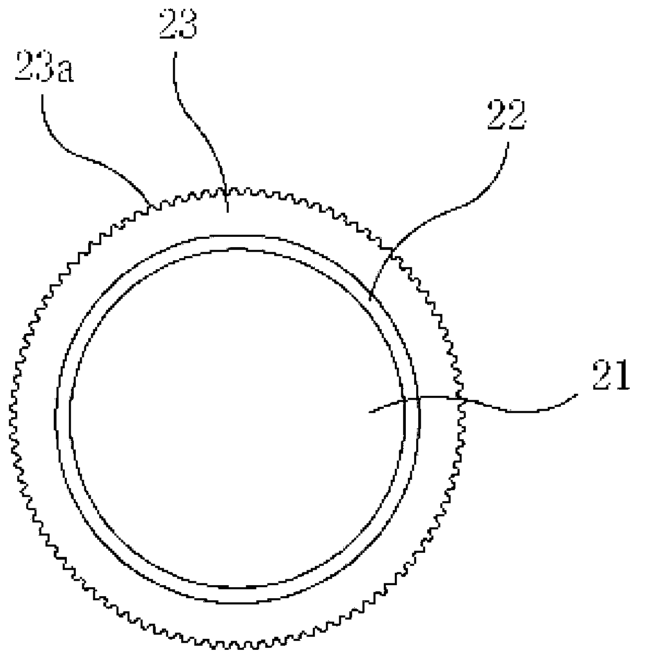
Disclosed are an electrode wire (2) for electro-discharge machining and a method for manufacturing the same, which reduce micro-particles generated when an electrode wire is subject to the electro-discharge machining and improving the machining speed and the surface roughness of a workpiece. The method includes preparing a wire rod, which includes a first metal (21) and has a first diameter, as a core wire, plating a second metal (23) on the core wire, performing a fine wire process for the core wire plated with the second metal so that the core wire has a second diameter, while forming a corrugation (23a, 24a) having a predetermined pattern on a surface of the core wire having a second diameter, and performing a heat treatment process to form a first alloy layer at a boundary surface between the core wire and the second metal through a mutual diffusion between the core wire and the second metal, and to form a second alloy layer at an outer portion of the first alloy layer through diffusion of the first metal toward the second metal.

Description

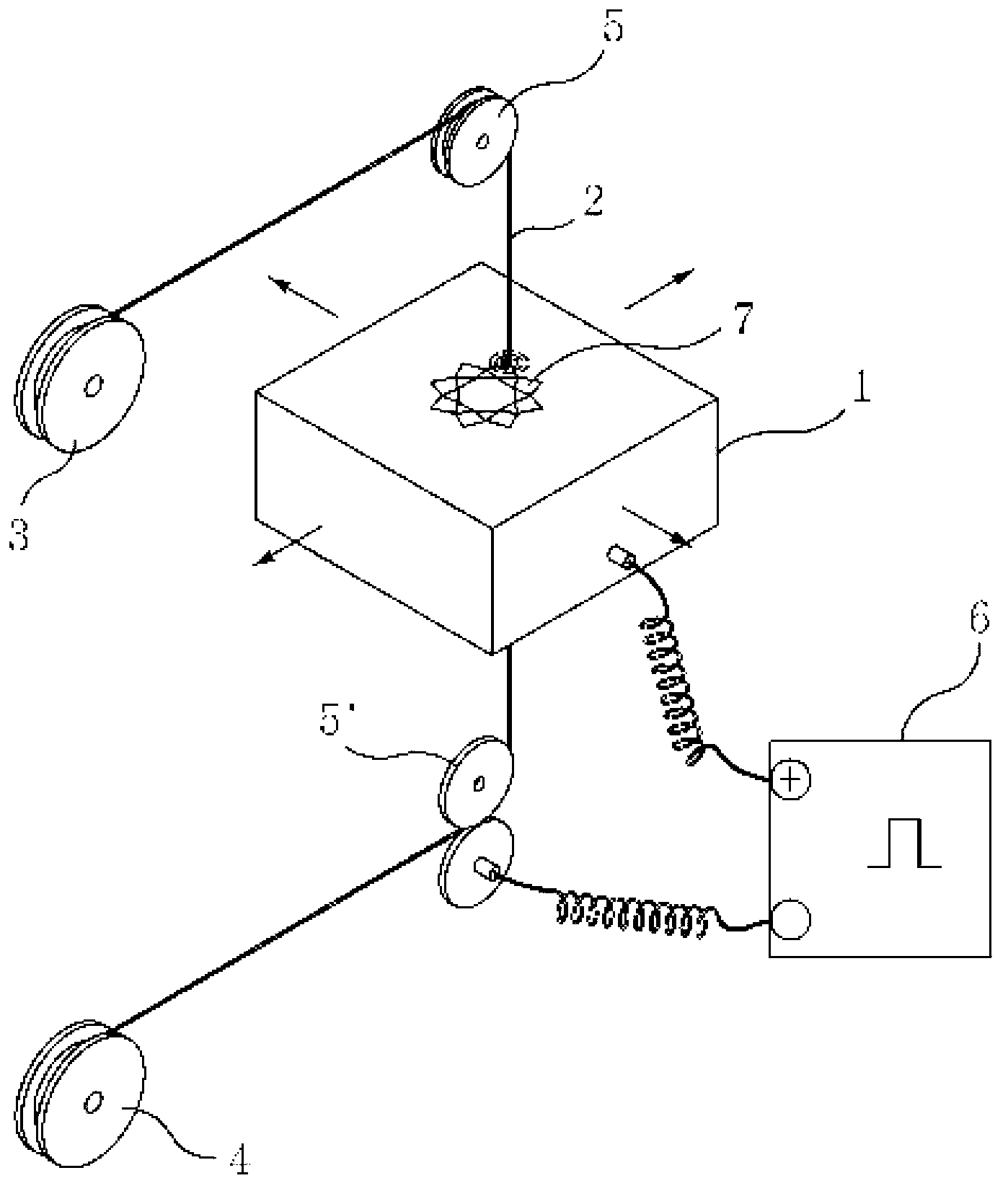
technical field [0001] The invention relates to a wire electrode for electro-discharge machining and a method for manufacturing the wire electrode. In particular, the present invention relates to a wire electrode for electric discharge machining and a method for manufacturing the same, which can reduce the time when the wire electrode is subjected to electric discharge machining. The particles produced can improve the processing speed and surface roughness of the workpiece. Background technique [0002] Such as figure 1 As shown, generally according to the electrical discharge machining method, a wire electrode 2 for electrical discharge machining is used, and the wire electrode 2 is inserted into the workpiece 1 through the starting hole 7 that has penetrated the workpiece 1 in advance. While the wire electrode 2 is continuously embedded in the workpiece 1 along the penetrating direction of the starting hole 7, a high-frequency voltage is applied between the wire electrod...

Claims


Application Information

Patent Timeline
Patent Type & Authority Applications(China)
IPC IPC(8): B23H1/04
CPCC25D5/50C23C28/023C25D7/0607C23C28/021B23H7/08C23C28/02B23H7/22B23H7/24C22C9/00C23C28/00
Inventor 成机哲成贤洙成贤国
Owner 欧佩克梅德美国有限责任公司
Why Eureka
Try Eureka