Bidirectional DC (direct current)/DC conversion device

A technology of conversion device and conversion unit, which is applied in the direction of output power conversion device, circuit device, battery circuit device, etc., can solve the problems of high conversion ratio and electromagnetic compatibility of suspended windings, which can not meet the requirements, and achieves simple circuit structure and cost reduction. , to achieve the effect of overvoltage

Inactive Publication Date: 2013-02-13
CONTEMPORARY AMPEREX TECH CO
View PDF9 Cites 40 Cited by
  • Summary
  • Abstract
  • Description
  • Claims
  • Application Information

AI Technical Summary

Problems solved by technology

[0004] In view of the problems existing in the prior art, the purpose of this application is to provide a bidirectional DC / DC conversion device to solve the problem of electromagnetic compatibility that may be introduced by using high transformation ratio and floating windings in the prior art
[0005] Another object of the present application is to provide a bidirectional DC / DC conversion device, which can solve the existing problems in the prior art that can only control the output voltage and current, but cannot meet the requirements of battery discharge balance. The bidirectional DC / DC converter can also control its The application requirements of the discharge current

Method used


Image

  • Bidirectional DC (direct current)/DC conversion device
  • Bidirectional DC (direct current)/DC conversion device
  • Bidirectional DC (direct current)/DC conversion device

Examples


Embodiment Construction

[0034] The present application will be described in further detail below in conjunction with the accompanying drawings and specific embodiments.

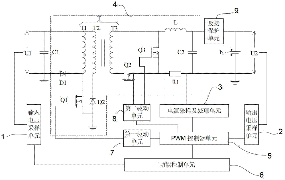
[0035] In order to solve the existing bidirectional DC / DC converter device with high transformation ratio, the floating winding will introduce large leakage inductance and parasitic parameters and generate interference, resulting in electromagnetic compatibility problems, and solve the problem that the existing bidirectional DC / DC converter only controls the output Voltage, current, and discharge current cannot be controlled. This application provides a new bidirectional DC / DC conversion device for balancing charge and discharge of battery cells in a high-voltage battery pack.

[0036] figure 1 The schematic circuit structure of the preferred embodiment of the present application is shown. It can be seen from the figure that the preferred embodiment includes, but not limited to: input voltage sampling unit 1, output voltage sampling...


PUM


Abstract

The invention relates to a bidirectional DC (direct current) / DC conversion device which comprises a power conversion unit, an input voltage sampling unit, an output voltage sampling unit, a current sampling and processing unit, a PWM (pulse width modulation) controller unit and a function control unit, wherein the power conversion unit is used for the conversion of different voltages; the input voltage sampling unit is used for detecting a first voltage signal of a voltage bus at the input end; the output voltage sampling unit is used for detecting a second voltage signal at the output end of the power conversion unit to judge whether a battery unit is in a constant-current charge stage or a constant-voltage charge state and whether an undervoltage situation occurs in the discharge process; the current sampling and processing unit is used for detecting a current signal passing through the battery unit; the PWM controller unit is used for generating a PWM signal having a certain duty ratio and adjusting the duty ratio of the PWM signal according to a feedback signal to meet work requirements of a circuit; and the function control unit is used for sending out an enable / discharge permission signal and a charge permission signal to control the operation of the PWM controller unit. According to the invention, the circuit structure is very simple and reliable, and the cost is reduced.

Description

technical field [0001] The present application relates to a voltage conversion device, in particular to a bidirectional DC / DC conversion device suitable for electronic equipment and new energy batteries. Background technique [0002] In the high-voltage battery pack of new energy vehicles and energy storage systems, in order to ensure that the battery system has sufficient charge / discharge capacity and prolong the service life of the battery pack, it is necessary to effectively balance the individual cells connected in series in the high-voltage battery pack. Most of the existing equalization technologies realize passive discharge equalization through resistance discharge. This is a one-way energy consumption equalization method. Can cause heat problems. [0003] At present, isolated bidirectional DC / DC converters are mainly used in solar energy storage control systems, electric vehicle motor drive and energy feedback systems, most of which are controlled by single-chip or ...

Claims


Application Information

Patent Timeline
Patent Type & Authority Applications(China)
IPC IPC(8): H02M3/335H02J7/00
Inventor 徐良渡林圣国潘约安
Owner CONTEMPORARY AMPEREX TECH CO
Why Eureka
Try Eureka