Laser transmission welding method for thermoplastic plastics

A technology of laser transmission welding and thermoplastics, which is applied in the field of laser welding, can solve the problems of non-conductivity, thermal conductivity change, difficulty in optimizing the range of laser welding process parameters, and two workpieces can no longer be separated, etc., to achieve enhanced strength and good conductivity / insulation effect

Inactive Publication Date: 2013-03-06
WENZHOU UNIVERSITY
View PDF2 Cites 6 Cited by
  • Summary
  • Abstract
  • Description
  • Claims
  • Application Information

AI Technical Summary

Problems solved by technology

However, the current laser transmission welding technology can only play the role of connection, and cannot change the properties of thermoplastic materials such as electrical conductivity and thermal conductivity afte

Method used


Image

  • Laser transmission welding method for thermoplastic plastics

Examples


Embodiment 1

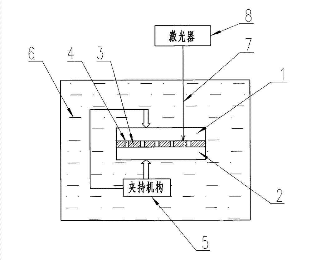
[0035] Such as figure 1 As shown, the invention provides a kind of laser transmission welding method of thermoplastics, comprising the following steps:

[0036] (1) A welding frame 3 is placed between two upper hard plastics 1 and lower hard plastics 2 to be welded; the upper hard plastic 1 is a thermoplastic that can transmit laser beams, and the welding frame 3 It is a hard material that can absorb laser beams. In the present embodiment, the upper hard plastic 1 and the lower hard plastic 2 adopt polyethylene terephthalate (PET) with a thickness of 10mm, and the lower hard plastic 2 adopts polyethylene terephthalate (PET). Carbonate (PC) with a thickness of 10mm; the welding skeleton 3 adopts a thin copper sheet with a thickness of 1mm; the melting point of the welding skeleton 3 is higher than that of the upper hard plastic 1 and the lower hard plastic 2, and the welding skeleton 3 There are several through holes 4; the position, size and shape of the through holes 4 can b...

Embodiment 2

[0045] The invention provides a thermoplastic laser transmission welding method, comprising the following steps:

[0046] (1) A welding frame 3 is placed between the two upper hard plastics 1 and the lower hard plastic 2 to be welded; the upper hard plastic 1 is a thermoplastic that can transmit laser beams; the welding frame 3 It is a hard material that can absorb laser beams, the melting point of the welding skeleton 3 is higher than the melting point of the upper hard plastic 1 and the lower hard plastic 2, and several through holes 4 are arranged on the welding skeleton 3; in this embodiment The upper hard plastic 1 is made of polycarbonate (PC) with a thickness of 50mm; the lower hard plastic 2 is made of polybutylene terephthalate (PBT) with a thickness of 100mm, and the welding skeleton 3 is made of aluminum oxide with a thickness of 0.5mm Ceramics;

[0047] (2) The upper hard plastic 1 and the lower hard plastic 2 are clamped by the clamping mechanism 5, that is, pres...


PUM

PropertyMeasurementUnit
Thicknessaaaaaaaaaa
Thicknessaaaaaaaaaa
Thicknessaaaaaaaaaa

Abstract

The invention provides a laser transmission welding method for thermoplastic plastics. The laser transmission welding method comprises the following steps of: (1) placing a weld skeleton between upper rigid plastic and lower rigid plastic; (2) enabling the upper rigid plastic, the weld skeleton and the lower rigid plastic to be in contact compaction; (3) placing the upper rigid plastic, the lower rigid plastic and the weld skeleton in cooling liquid; (4) enabling a laser beam to enter from one side of the upper rigid plastic, and focus on the weld skeleton so as to form a weld point; (5) melting the upper rigid plastic and the lower rigid plastic which are in contact with the weld point; (6) the molten plastic is in mutual penetrating fusion through a through hole, close to the weld point, in the weld skeleton; (7) stopping irradiation and removing the laser beam; and (8) repeating the steps (4)-(7). The laser transmission welding method for the thermoplastic plastics has the advantages that the welding path and welding strength can be accurately controlled, the overall strength and rigidity of welded members are improved, the original properties of materials at local parts of welded joints are randomly changed, the occurrence of firing defects is prevented, and the welding connection and separation can be repeatedly realized.

Description

technical field [0001] The invention belongs to the field of laser welding, and in particular relates to a thermoplastic laser transmission welding method. Background technique [0002] Thermoplastics are the most widely used plastics. It is a type of plastic formulated with thermoplastic resin as the main component and various additives. Under certain temperature conditions, plastics can soften or melt into any shape, and the shape remains unchanged after cooling; this state can be repeated many times and always has plasticity, and this repetition is only a physical change, which is called thermoplastic. plastic. Polyethylene, polypropylene, polyvinyl chloride, polystyrene, polyoxymethylene, polycarbonate, polyamide, acrylic plastics, other polyolefins and their copolymers, polysulfone, polyphenylene ether, chlorinated polyether, etc. thermoplastic. The resin molecular chains in thermoplastics are all linear or branched. There is no chemical bond between the molecular ch...

Claims


Application Information

Patent Timeline
IPC IPC(8): B29C65/16
CPCB29C66/73921B29C65/1616B29C65/1635B29C65/1638B29C65/1654B29C65/168B29C66/0016B29C66/1122B29C66/30341B29C66/3494B29C66/41B29C66/71B29C66/712B29C66/7352B29C66/83221B29C66/919B29K2509/02B29K2705/10B29K2077/00B29K2023/06B29K2023/12B29K2067/003B29K2025/06B29K2055/02B29K2033/12B29K2069/00B29K2067/006
Inventor 曹宇李峰平赵宗礼王陇花李剑阳
Owner WENZHOU UNIVERSITY
Why Eureka
Try Eureka