Fluorescence anisotropic microscopic imaging device and method with dual-channel and single-light path structure

An anisotropic and microscopic imaging technology, which is applied in measuring devices, fluorescence/phosphorescence, and material analysis through optical means, can solve the problems of low cost and low imaging accuracy, simplify the structure, improve imaging accuracy, and avoid The effect of the influence of the Magic angle

Inactive Publication Date: 2016-12-21
GUANGDONG UNIV OF TECH
View PDF5 Cites 0 Cited by
  • Summary
  • Abstract
  • Description
  • Claims
  • Application Information

AI Technical Summary

Problems solved by technology

[0005] Aiming at the disadvantages of the current fluorescence anisotropy microscopic imaging system, such as relatively complex and low imaging precision, the present invention proposes a fluorescence anisotropic microscopic imaging device and method with a dual-channel, single-light-path structure, through the method of time-sharing imaging, Make the two polarized light imaging systems share the same optical path, reduce the calculation error of ill-conditioned matrix caused by the phase difference of the optical system, the accuracy of fluorescence anisotropy imaging is higher, and the system structure is simplified and the cost is lower

Method used


Image

  • Fluorescence anisotropic microscopic imaging device and method with dual-channel and single-light path structure
  • Fluorescence anisotropic microscopic imaging device and method with dual-channel and single-light path structure
  • Fluorescence anisotropic microscopic imaging device and method with dual-channel and single-light path structure

Examples


Embodiment Construction

[0023] The present invention is described in detail below in conjunction with accompanying drawing and embodiment:

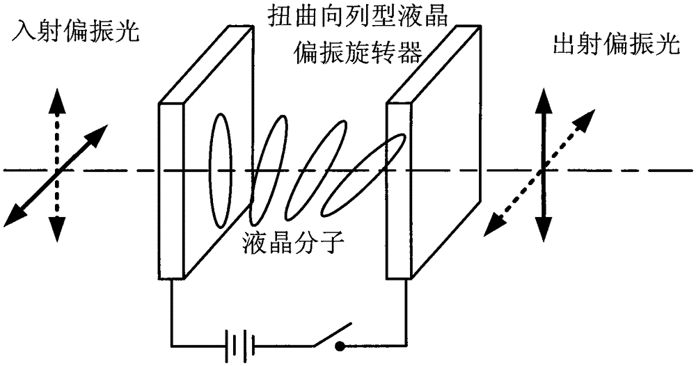
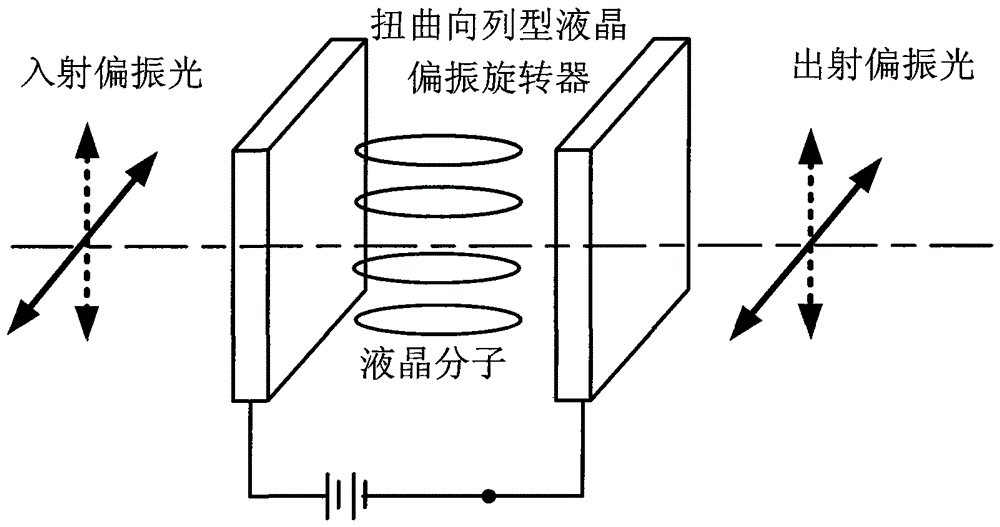
[0024] The structure of the fluorescent anisotropic microscopic imaging device with dual channels and single optical path structure proposed by the present invention is as follows: image 3 As shown, it includes in turn: excitation light source (1), lens group (2), polarizer (3), excitation filter (4), beam splitter (5), objective lens (6), sample workbench (7), Sample (8), emission filter (9), twisted nematic liquid crystal polarization rotator (10), analyzer (11), digital camera (12), computer (13), high-precision low-ripple current source ( 14) and control circuit (15).

[0025] In this embodiment, the sample (8) is rhodamine 6G plus 90% glycerol aqueous solution, and the excitation light source (1) is a high-brightness LED. The illumination intensity of the Lambertian distribution emitted by the excitation light source (1) is converted into a Gaussian inte...


PUM


Abstract

The invention relates to a dual-channel and single light path structure fluorescent anisotropic microscopic imaging device and a fluorescent anisotropic microscopic imaging method, which are suitable for transmission and reflection type microscopes. In the fluorescent anisotropic microscopic imaging device, a twisted nematic liquid crystal polarization rotator and a polarization analyzer are positioned on a fluorescence imaging light path, and the rotation center of the twisted nematic liquid crystal polarization rotator is coincident with the center of an optical axis of the fluorescence imaging light path, and the polarization direction of a polarizer, the polarization detection direction of the polarization analyzer, and the liquid crystal molecule arrangement direction on one side of incident light of the twisted nematic liquid crystal polarization rotator are parallel. According to the fluorescent anisotropic microscopic imaging method provided by the invention, the time-sharing control twisted nematic liquid crystal polarization rotator outputs a polarization state of light by switching high and low level signals, two tested sample fluorescence images, which are mutually perpendicular to the polarization direction, are correspondingly shot by a digital camera, and finally, fluorescent anisotropic microscopic images of the tested samples are calculated. On the premise of enhancing the fluorescent anisotropic imaging precision, the fluorescent anisotropic microscopic imaging device and the fluorescent anisotropic microscopic imaging method can fully utilize the view field of the digital camera, simplify the system structure, and make the cost lower.

Description

technical field [0001] The invention relates to a method and an instrument for fluorescent anisotropic microscopic imaging, in particular to a device and method for performing fluorescent anisotropic microscopic imaging of materials, biological and chemical samples by means of a wide-field transmission or reflection fluorescent microscope. Background technique [0002] Fluorescence microscopy imaging technology can observe living cells in the normal state of biological samples, maintaining the real environment of samples to the greatest extent. Fluorescence anisotropy is a phenomenon in which a fluorophore is excited by linearly polarized light, and its fluorescence varies along the light intensity of different polarization directions. In biochemical research and applications, the analysis of fluorescence anisotropy on fluorescently labeled samples can provide information such as the temperature, pH value and movement diffusion speed of the local environment of fluorescent m...

Claims


Application Information

Patent Timeline
Patent Type & Authority Patents(China)
IPC IPC(8): G01N21/01G01N21/64
Inventor 周延周陈辞
Owner GUANGDONG UNIV OF TECH
Why Eureka
Try Eureka