New cavity dielectric cavity filter
A dielectric cavity and filter technology, applied in the field of reciprocal microwave devices, achieves the effects of good temperature characteristics, low loss and small volume
- Summary
- Abstract
- Description
- Claims
- Application Information
AI Technical Summary
Problems solved by technology
Method used
Image
Examples
Embodiment 1~3
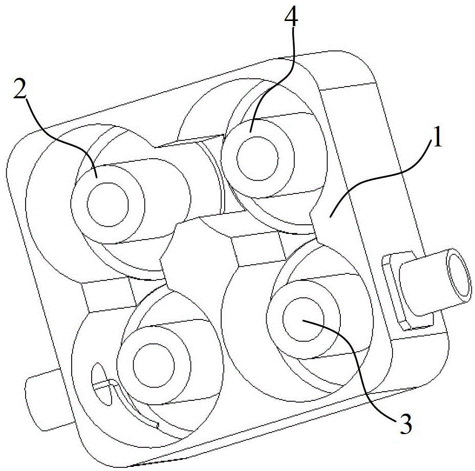
[0050]Embodiments 1 to 3: A novel cavity dielectric cavity filter, comprising a cavity 1 and a dielectric resonator 2, the dielectric resonator is a cylinder 4 with a through hole 3; the dielectric resonator 2 consists of the following The component composition of mass percentage content is as shown in table 1:
[0051] Table 1
[0052]
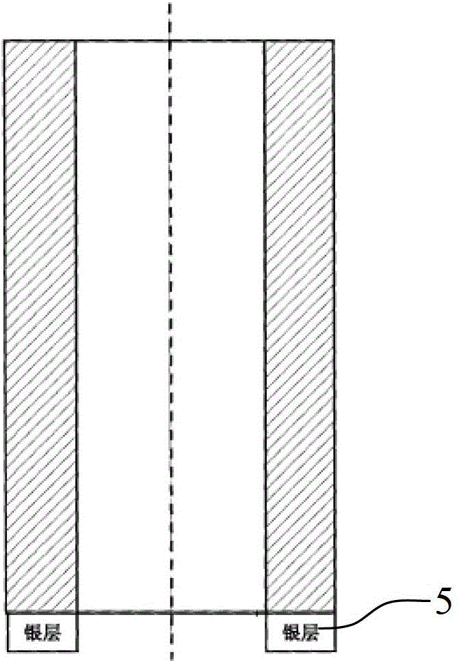
[0053] One end of the dielectric resonator 2 is plated with a silver layer 5, and the other end of the dielectric resonator 2 is welded in the cavity 1;
[0054] The cavity 1 is composed of the following components in mass percentage as shown in Table 2:
[0055] Aluminum oxide calcium carbonate Lanthanum oxide Samarium oxide Example 1 95% 3% 1.5% 0.5% Example 2 95.5% 3% 1.1 % 0.4% Example 3 96% 2.5% 1 % 0.5%
[0056] The dielectric constant of the cavity 1 is 9.5.
[0057] The above-mentioned dielectric resonator 2 is composed of the following components in mass percentag...
PUM
| Property | Measurement | Unit |
|---|---|---|
| thickness | aaaaa | aaaaa |
| frequency temperature coefficient | aaaaa | aaaaa |
| relative permittivity | aaaaa | aaaaa |
Abstract
Description
Claims
Application Information
 - R&D
- Intellectual Property
- Life Sciences
- Materials
- Tech Scout
- Unparalleled Data Quality
- Higher Quality Content
- 60% Fewer Hallucinations
Browse by: Latest US Patents, China's latest patents, Technical Efficacy Thesaurus, Application Domain, Technology Topic, Popular Technical Reports.
© 2025 PatSnap. All rights reserved.Legal|Privacy policy|Modern Slavery Act Transparency Statement|Sitemap|About US| Contact US: help@patsnap.com


