Sub-wavelength extreme ultraviolet metal transmission grating and manufacture method thereof

A transmission grating and extreme ultraviolet technology, which is applied in the direction of diffraction grating, optics, and optomechanical equipment, can solve the problems that the thickness of the resist is difficult to meet the use requirements, and the resist is easy to collapse, so as to reduce the difficulty of processing and improve the transmittance. pass rate, reducing the effect of backscattering

Active Publication Date: 2013-04-03
INST OF MICROELECTRONICS CHINESE ACAD OF SCI
View PDF0 Cites 8 Cited by
  • Summary
  • Abstract
  • Description
  • Claims
  • Application Information

AI Technical Summary

Problems solved by technology

[0007] In view of this, the main purpose of the present invention is to propose a sub-wavelength extreme ultraviolet metal transmission grating and its manufacturing method, to solve the problem of the application of the transmission enhancement effect of the sub-wavelength metal transmission grating in the extreme ultraviolet band, and to solve the problem in the production of traditional high When the linear density duty ratio is 1:1 metal transmission grating, due to the proximity effect and back scattering, the resist is easy to collapse, and the thickness of the resist is difficult to meet the use requirements, so as to ensure that the fabricated structure can be aligned with the electrode at the same time. Phase and amplitude modulation of incident light in the ultraviolet band

Method used


Image

  • Sub-wavelength extreme ultraviolet metal transmission grating and manufacture method thereof
  • Sub-wavelength extreme ultraviolet metal transmission grating and manufacture method thereof
  • Sub-wavelength extreme ultraviolet metal transmission grating and manufacture method thereof

Examples


Embodiment Construction

[0023] In order to make the object, technical solution and advantages of the present invention clearer, the present invention will be described in further detail below in conjunction with specific embodiments and with reference to the accompanying drawings.

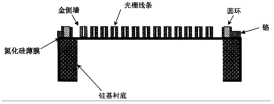
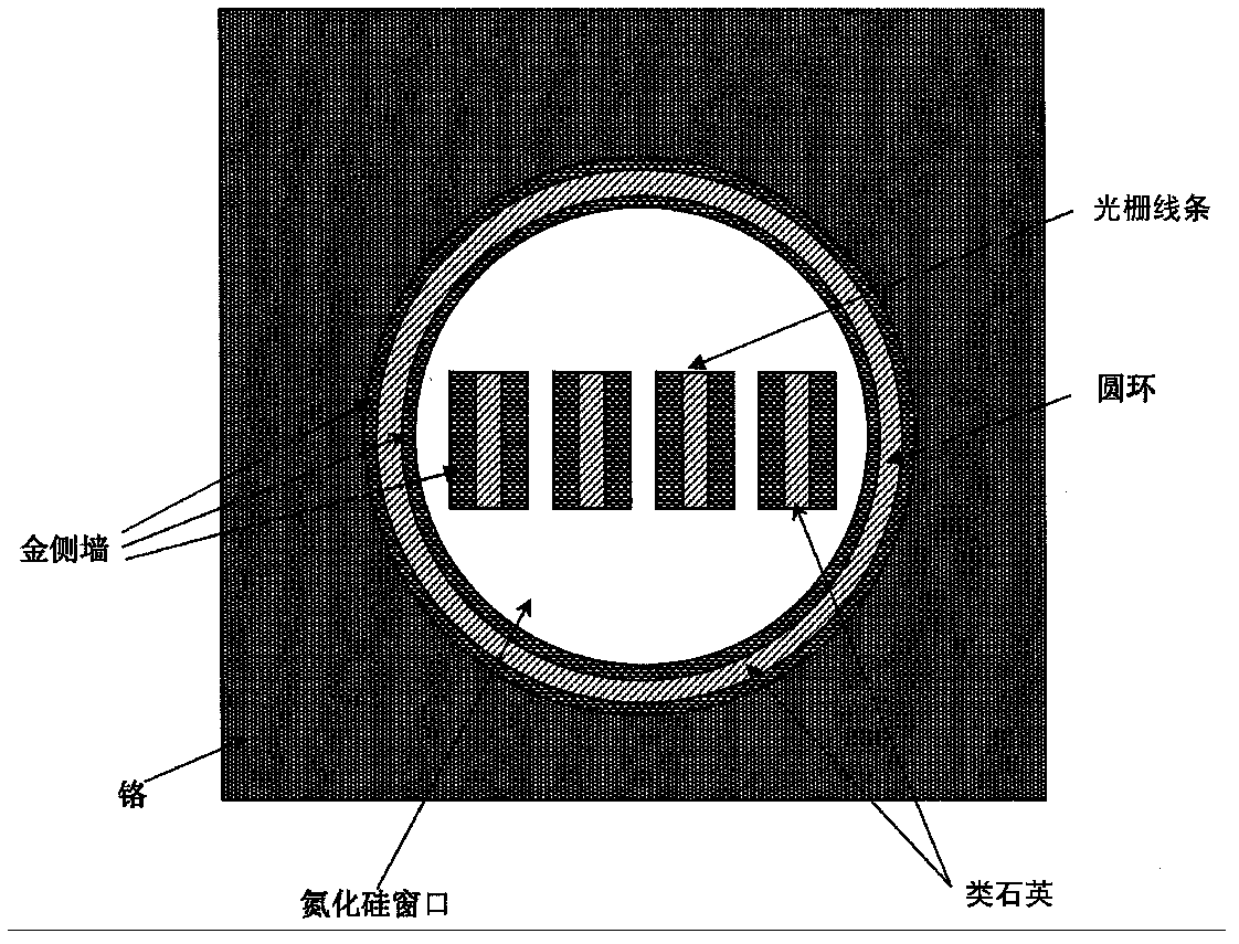
[0024] Such as figure 1 with figure 2 as shown, figure 1 with figure 2 Respectively show a cross-sectional view and a top view of a sub-wavelength EUV metal transmission grating according to an embodiment of the present invention, the sub-wavelength EUV metal transmission grating includes: a silicon-based substrate supporting a silicon nitride self-supporting thin film window, a supporting grating line A silicon nitride self-supporting film window, a plurality of grating lines for phase modulation of incident light on the silicon nitride self-supporting film window, and a ring surrounding the multiple grating lines, and a silicon nitride self-supporting film window on the silicon nitride self-supporting film window G...


PUM

PropertyMeasurementUnit
thicknessaaaaaaaaaa
thicknessaaaaaaaaaa
widthaaaaaaaaaa

Abstract

The invention discloses a sub-wavelength extreme ultraviolet metal transmission grating and a manufacture method of the sub-wavelength extreme ultraviolet metal transmission grating. The manufacture method of the sub-wavelength extreme ultraviolet metal transmission grating comprises the steps of manufacturing a silicon nitride self-supporting film window on the back of a double-sided polishing silicon substrate, coating an electron beam resist HSQ (polyhedral octahydridospherosiloxane) on a silicon nitride film on the front side of the silicon substrate in a rotating mode, carrying out electron beam direct-writing lithography to HSQ, forming grating lines and a ring surrounding the grating lines, and fixing photography to obtain graphs of grating lines graph and the ring after the development; depositing a chromium material on the front side of the silicon substrate by the silicon substrate magnetron sputtering to be used as light blocking layers on around the graphs of the grating lines and the ring, eliminating the chromium material in the graph of the ring, and only maintaining the chromium material outside the graph of the ring to be used as an absorbent for absorbing stray light; generating a metal material on the front side of the silicon substrate by adopting an atomic layer deposition technology; and eliminating the metal material deposited on the chromium material outside the graph of the ring, among the graphs of the grating lines, and on the graphs of the grating lines, and maintaining the metal material on the side wall of the graphs of the grating lines.

Description

technical field [0001] The invention relates to the technical field of micro-optical metal transmission gratings, in particular to a sub-wavelength extreme ultraviolet metal transmission grating and a manufacturing method thereof. Background technique [0002] Transmission grating is a very widely used and very important high-resolution dispersive optical element. It has the advantages of simple structure, wide spectral range, smooth energy response, flat spectral surface, etc., and can be easily compared with time and space resolution instruments. Combined, a measurement system capable of simultaneously diagnosing plasma temporal and spatial energy spectral characteristics is formed, so transmission gratings are widely used in astrophysics and inertial confinement nuclear fusion. As a kind of transmission grating, the sub-wavelength metal transmission grating also plays an important role in the above applications. [0003] When the light wave irradiates the surface of the ...

Claims


Application Information

Patent Timeline
Patent Type & Authority Applications(China)
IPC IPC(8): G02B5/18G03F7/00
Inventor 李海亮谢常青刘明李冬梅史丽娜朱效立
Owner INST OF MICROELECTRONICS CHINESE ACAD OF SCI
Why Eureka
Try Eureka