
Waste heat recovery system of automobile exhaust pipe and control method thereof

A technology for waste heat recovery and automobile exhaust, which is used in exhaust devices, mufflers, internal combustion piston engines, etc., can solve the problem of catalytic converter catalyst sintering into agglomerates, affecting the reliability of baffles and their actuators, and failing to make full use of them energy and other issues, to achieve the effect of improving efficiency, preventing sintering agglomeration failure, and being easy to promote and use

Inactive Publication Date: 2013-04-17
NINGBO UNIVERSITY OF TECHNOLOGY
View PDF6 Cites 3 Cited by
  • Summary
  • Abstract
  • Description
  • Claims
  • Application Information

AI Technical Summary

Problems solved by technology

The disadvantage of this patent is that thermoelectric materials used for waste heat power generation in automobile exhaust pipes can be divided into high-temperature materials and medium-temperature materials according to different temperature application ranges. Thermoelectric modules with different thermoelectric materials have large ZT values ​​and high power generation efficiency within a certain temperature range. High, but when the temperature exceeds this range, the ZT value becomes smaller and the power generation efficiency is very low. Since the temperature of the exhaust gas emitted by the engine changes frequently, the heat and electricity recovery system can only work when the temperature reaches a certain level. Utilizes energy, resulting in less efficient power generation
In addition, due to the constantly changing high-temperature environment of the exhaust gas of the vehicle engine, the baffle is susceptible to alternating thermal stress shocks. The expansion and contraction deformation caused by thermal stress shocks and the wear of the kinematic pair caused by frequent turning will seriously affect the performance of the baffle and its actuators. Reliability, the failure of the diversion control of the baffle will cause the catalyst of the catalytic converter to sinter into agglomerates and fail, and the frequent flipping of the baffle will also produce impact noise

Method used


Image

  • Waste heat recovery system of automobile exhaust pipe and control method thereof
  • Waste heat recovery system of automobile exhaust pipe and control method thereof

Examples


Embodiment Construction

[0044] The principles and features of the present invention are described below in conjunction with the accompanying drawings, and the examples given are only used to explain the present invention, and are not intended to limit the scope of the present invention.

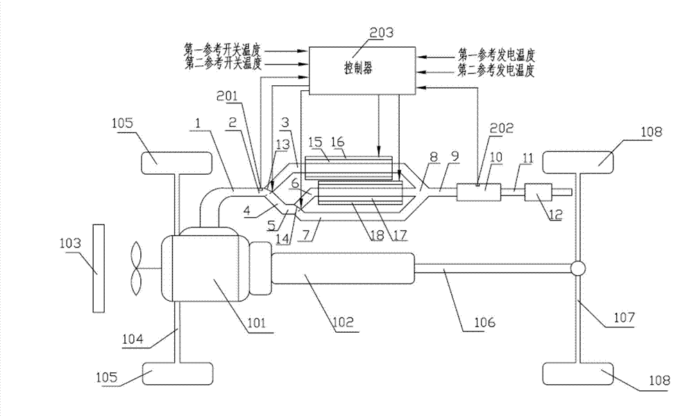
[0045] like figure 1 The shown car includes: front axle 104, front wheel 105, drive shaft 106, rear axle 107, rear wheel 108 jointly form a vehicle frame structure, engine 101, gearbox 102 and radiator 103 are included on the vehicle frame.

[0046] A waste heat recovery system for an automobile exhaust pipe, comprising a first exhaust main pipe 1 for discharging engine exhaust gas, the output port of the first exhaust main pipe 1 is respectively connected to the first exhaust branch pipe 3 through the first tee 2 The input port of the input port and the exhaust sub-conduit 4, the output port of the exhaust sub-conduit 4 is respectively connected to the input port of the second exhaust branch pipe 6 and the input po...


PUM


Abstract

The invention relates to a waste heat recovery system of an automobile exhaust pipe and a control method of the waste heat recovery system. Combining characteristics of the waste heat recovery system, the waste heat recovery system with high waste heat recovery efficiency is obtained through increasing of a new branch pipe structure and the control method of the waste heat recovery system, reliability and efficiency of energy conversion are improved, and motion frequency of a baffle and a cold source valve is reduced simultaneously. In addition, through increasing of control of cold quantity of the cold source, actual temperature of a catalytic converter cannot be too high, and the problem that sintering agglomerate failure caused by too high temperature of catalyst is solved.

Description

technical field [0001] The invention relates to the field of exhaust waste heat recovery, in particular to an automobile exhaust pipe waste heat recovery system and a control method thereof. Background technique [0002] Most of the existing automobile waste heat recovery devices use the waste heat of automobile exhaust to generate electricity, and store the electric energy in the vehicle battery, which reduces pollution and improves energy utilization. In the automobile exhaust system, a catalytic converter is often used. The function of the catalytic converter is to decompose incompletely burned hydrocarbons, CO and various nitrogen oxides in the exhaust gas generated by the combustion of hydrocarbon fuels. Usually, the honeycomb ceramic substrate inside the catalytic converter is coated with a small amount of precious metal particles such as platinum, rhodium and palladium. When the exhaust gas flows through, the harmful components will be oxidized and reduced by the prec...

Claims


Application Information

Patent Timeline
Patent Type & Authority Applications(China)
IPC IPC(8): F01N5/02F01N13/08
CPCY02T10/12
Inventor 赵付舟胡如夫黄永青汪秀敏
Owner NINGBO UNIVERSITY OF TECHNOLOGY
Learn More