Oxidation-reduction resin film oxygen removal equipment and oxygen removal method thereof

A technology for deoxidizing equipment and resin membranes, which can be used in reduction water/sewage treatment, oxidized water/sewage treatment, degassed water/sewage treatment, etc., and can solve the problems of high manufacturing cost, high operating cost and high price.

Active Publication Date: 2014-08-20
霍银坤
View PDF4 Cites 0 Cited by
  • Summary
  • Abstract
  • Description
  • Claims
  • Application Information

AI Technical Summary

Problems solved by technology

In the existing water treatment, there are methods and equipment such as thermal deaeration, sponge iron deaeration (also known as normal temperature filter deaeration), vacuum deaeration, desorption deaeration and redox resin deaeration, etc., although redox resin deaeration The method has other deaeration methods such as thermal deaeration, sponge iron deaeration (also known as normal temperature filter deaeration), vacuum deaeration, desorption deaeration, etc., which cannot have the characteristics at the same time. However, redox resin deaerators still exist Some shortcomings and deficiencies need to be further improved. For example, the resin deaerator regenerated with hydrazine cannot be used for deaeration of boiler feed water in food-related industries, and the redox resin deaerator regenerated with hydrogen reduction is green and environmentally friendly, but the manufacturing cost is high , high price, difficult for users to accept
The redox resin deaerator regenerated with sodium sulfite has low manufacturing cost and low price, but the consumption of regeneration agent is large and the operating cost is high (consumption of anhydrous sodium sulfite per ton of water is 150-200 grams

Method used


Image

  • Oxidation-reduction resin film oxygen removal equipment and oxygen removal method thereof
  • Oxidation-reduction resin film oxygen removal equipment and oxygen removal method thereof
  • Oxidation-reduction resin film oxygen removal equipment and oxygen removal method thereof

Examples


Embodiment 1—5

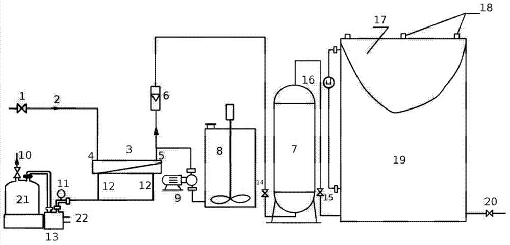
[0047] In redox resin membrane deoxygenation equipment of the present invention ( figure 1 ), where the membrane separation deaerator is 150×800mm. It consists of water inlet valve 1, membrane separation module 3, membrane separation module inlet pipe 4, membrane separation module outlet pipe 5, vacuum pump exhaust valve 10, vacuum pressure gauge 11, vacuum pump suction pipe and membrane separator air chamber suction pipe 12, The water ring vacuum pump 13 and the circulating cooling water inlet and outlet pipes 22 are composed: the water inlet valve 1 is connected to the membrane separation module 3 through the membrane separation module inlet pipe 4, and the membrane separation module outlet pipe 5 is connected to the bottom of the downstream redox resin deaerator 7 through the pipeline connected to each other, and a flow meter 6 and a floating bed resin deaerator water inlet valve 14 are arranged on the connected pipeline, the vacuum pump exhaust valve 10 is set on the top o...


PUM

PropertyMeasurementUnit
thicknessaaaaaaaaaa
diameteraaaaaaaaaa

Abstract

The invention relates to oxidation-reduction resin film oxygen removal equipment and an oxygen removal method thereof. The oxygen removal method comprises physical oxygen removal by a film separation oxygen removal device and chemical oxygen removal by an oxidation-reduction resin oxygen removal device, wherein after oxygen is removed by the oxygen removal devices, the content of residual oxygen in water is less than or equal to 10ppb. The oxidation-reduction resin film oxygen removal equipment and the oxygen removal method thereof provided by the invention fully combine the advantages of physical oxygen removal and chemical oxygen removal, have the advantages of greatly reducing the consumption of a reducing agent, reducing the size of the oxygen removal devices, lowering cost and price, saving energy, being environmentally-friendly and having low power consumption. The oxidation-reduction resin film oxygen removal equipment and the oxygen removal method are a new generation of oxidation-reduction resin film oxygen removal equipment and oxygen removal method thereof and can be widely applied to fields such as oxygen removal of reinjection seawater in offshore oilfields, oxygen removal of injected water in land oilfields, oxygen removal of fed water in hot water boilers and steam boilers, oxygen removal of cooling water and oxygen removal of steam condensate.

Description

technical field [0001] The invention belongs to the field of water treatment technology and equipment, and in particular relates to a redox resin film deoxygenation equipment and a deoxygenation method which adopts the combination of chemical and physical deoxygenation principles. Background technique [0002] Dissolved oxygen in water undergoes electrochemical reaction corrosion on the steel surface. The cementite is used as the anode, the ferrite absorbs oxygen as the cathode, and the anion and cation in the water play the role of transmitting chemical current. In this way, countless primary batteries composed of countless galvanic cells cause the steel surface to be corroded. Because this electrochemical corrosion is non-uniform corrosion, many small pits will eventually be formed on the steel, causing perforation of the boiler equipment. Therefore, for industrial boilers, high-pressure boilers in power plants, and ultra-high-pressure boilers, there are strict regulations...

Claims


Application Information

Patent Timeline
Patent Type & Authority Patents(China)
IPC IPC(8): C02F1/20C02F1/44C02F1/70C02F1/72
Inventor 陈四海霍银坤霍秀岩霍秀峰周立友
Owner 霍银坤
Why Eureka
Try Eureka