Direct reduction process for sponge iron production implemented by using non-catalytic conversion of CH4

A non-catalytic, sponge iron technology, applied in the field of iron or steel smelting, can solve the problems of long process flow, complex process route, insufficient conversion, etc., and achieve strong controllability of process parameters, simple process flow, and preheating temperature. low effect

Active Publication Date: 2013-06-12
CISDI ENG CO LTD
View PDF4 Cites 19 Cited by
  • Summary
  • Abstract
  • Description
  • Claims
  • Application Information

AI Technical Summary

Problems solved by technology

[0005]1) Use coke oven gas and shaft furnace top gas after purification and decarburization, humidify and then heat to about 1000℃ to enter the shaft furnace to reduce iron ore, The key to this technical route is to use high temperature and the catalysis of sponge iron to modify part of CH4 to generate CO+H2 supplementary reducing gas, but this process route Decarburization and oxygen injection are required to raise the temperature. At the same time, at a temperature of about 1000 ° C, if the reducing gas atmosphere is not well controlled, there will be defects that the sponge iron is easy to bond;
[0006]2)) Use oxygen, coke oven gas, carbon dioxide, and water vapor to transform in the reformer, then mix with top gas, desulfurize and decarbonize, and then heat to Enter the shaft furnace at 800°C to reduce iron ore, and at the same time require H2 / CO>1.5; The high-temperature gas is cooled first and then heated, which has the disadvantages of low raw material gas utilization efficiency and high energy consumption;
[0008] In summary, the current domestic technical route for methane-rich gas-based shaft furnace direct reduction processes such as natural gas and coke oven gas has long process flow and conversion process Technical defects such as complexity, insufficient conversion, and easy sticking of the shaft furnace

Method used


Image

  • Direct reduction process for sponge iron production implemented by using non-catalytic conversion of CH4

Examples


no. 1 example

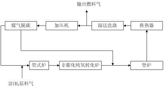
[0038] This example utilizes CH 4 The direct reduction process for the production of sponge iron by non-catalytic conversion is:

[0039] The purified and pressure-regulated rich CH 4 The raw material gas and the furnace top gas output from the shaft furnace and obtained after cooling, dust removal, dehydration, pressurization, and decarburization enter the tube furnace together for preheating, and the preheating temperature is 400°C. The CH-enriched 4 The raw material gas is coke oven gas;

[0040] The preheated coal gas enters the non-catalytic pure oxygen reformer, where it undergoes a combustion reaction with oxygen and rapidly raises the temperature to 1300°C. CH 4 Non-catalytic conversion to CO+H 2 ;

[0041] The high-temperature gas discharged from the non-catalytic pure oxygen reformer is mixed with the top gas which has been cooled, dedusted, pressurized and decarburized at the front end, and then enters the shaft furnace to reduce iron ore to produce sponge iron;...

no. 2 example

[0044] This example utilizes CH 4 The direct reduction process for the production of sponge iron by non-catalytic conversion is:

[0045] The purified and pressure-regulated rich CH 4 The raw material gas and the furnace top gas output from the shaft furnace and obtained after cooling, dust removal, dehydration, pressurization, and decarburization enter the tube furnace together for preheating, and the preheating temperature is 380°C. The CH-rich gas in this embodiment 4 The feed gas is natural gas;

[0046] The preheated gas enters the non-catalytic pure oxygen reformer, where it undergoes a combustion reaction with oxygen and rapidly raises the temperature to 1200°C to convert CH 4 Non-catalytic conversion to CO+H 2 ;

[0047] The high-temperature gas discharged from the non-catalytic pure oxygen reformer is mixed with the top gas which has been cooled, dedusted, pressurized and decarburized at the front end, and then enters the shaft furnace to reduce iron ore to produc...

no. 3 example

[0050] This example utilizes CH 4 The direct reduction process for the production of sponge iron by non-catalytic conversion is:

[0051] The purified and pressure-regulated rich CH 4 The raw material gas and the furnace top gas output from the shaft furnace and obtained after cooling, dust removal, dehydration, pressurization, and decarburization enter the tube furnace together for preheating, and the preheating temperature is 350°C. The CH-enriched 4 The raw material gas is coke oven gas;

[0052] The preheated coal gas enters the non-catalytic pure oxygen reformer, where it undergoes a combustion reaction with oxygen and rapidly raises the temperature to 1400°C. CH 4 Non-catalytic conversion to CO+H 2 ;

[0053] The high-temperature gas discharged from the non-catalytic pure oxygen reformer is mixed with the top gas which has been cooled, dedusted, pressurized and decarburized at the front end, and then enters the shaft furnace to reduce iron ore to produce sponge iron;...


PUM


Abstract

The invention discloses a direct reduction process for sponge iron production implemented by using the non-catalytic conversion of CH4, and the direct reduction process comprises the following steps: feeding a feed gas rich in CH4 and subjected to purification and pressure regulation and a stock gas output by a shaft furnace and subjected to cooling, dust removal, pressurization and decarburization into a tube furnace together and preheating; feeding the preheated coal gas into a non-catalytic pure oxygen reforming furnace, performing combustion reaction and heating on the preheated coal gas and oxygen in the non-catalytic pure oxygen reforming furnace, and performing non-catalytic conversion on the CH4 so as to generate CO+H2; after the high-temperature coal gas discharged from the non-catalytic pure oxygen reforming furnace and the stock gas discharged at the front end and subjected to cooling, dust removal, pressurization and decarburization are mixed and cooled, feeding the mixed gas into the shaft furnace and reducing iron ores, thereby producing sponge irons; and after the stock gas discharged from the shaft furnace is subjected to cooling, dust removal, pressurization and decarburization, feeding part of the stock gas and the supplementary feed gas rich in CH4 into the tube furnace and the non-catalytic pure oxygen reforming furnace together, wherein the other part of the stock gas is used as the cold-doped coal gas of the high-temperature coal gas discharged from the non-catalytic pure oxygen reforming furnace. Because the preheating temperature is low, no carbon precipitation occurs, and no strict limitation on the H2S content of the feed gas rich in CH4 exits, so that the bonding of the sponge irons can be prevented.

Description

technical field [0001] The invention belongs to the technical field of iron or steel smelting, and in particular relates to a 4 A direct reduction process for the production of sponge iron by non-catalytic conversion. Background technique [0002] The iron and steel industry is the basic industry of the national economy, and it is also a key industry in my country's energy resource consumption and pollution discharge. In order to speed up structural adjustment and industrial upgrading of the iron and steel industry, change the development mode of the iron and steel industry, and promote economical, clean and sustainable development, the state proposed in the "Steel Industry Adjustment and Revitalization Plan" to "strengthen non-blast furnace smelting-steelmaking, refining-direct Rolling new process clean process technology research and development and testing" as a key task to promote energy conservation and emission reduction in the whole industry, fully promote clean prod...

Claims


Application Information

Patent Timeline
Patent Type & Authority Applications(China)
IPC IPC(8): C21B13/02
CPCY02P10/143
Inventor 陈凌郭敏张涛吴开基鹿存房林亮成
Owner CISDI ENG CO LTD
Why Eureka
Try Eureka