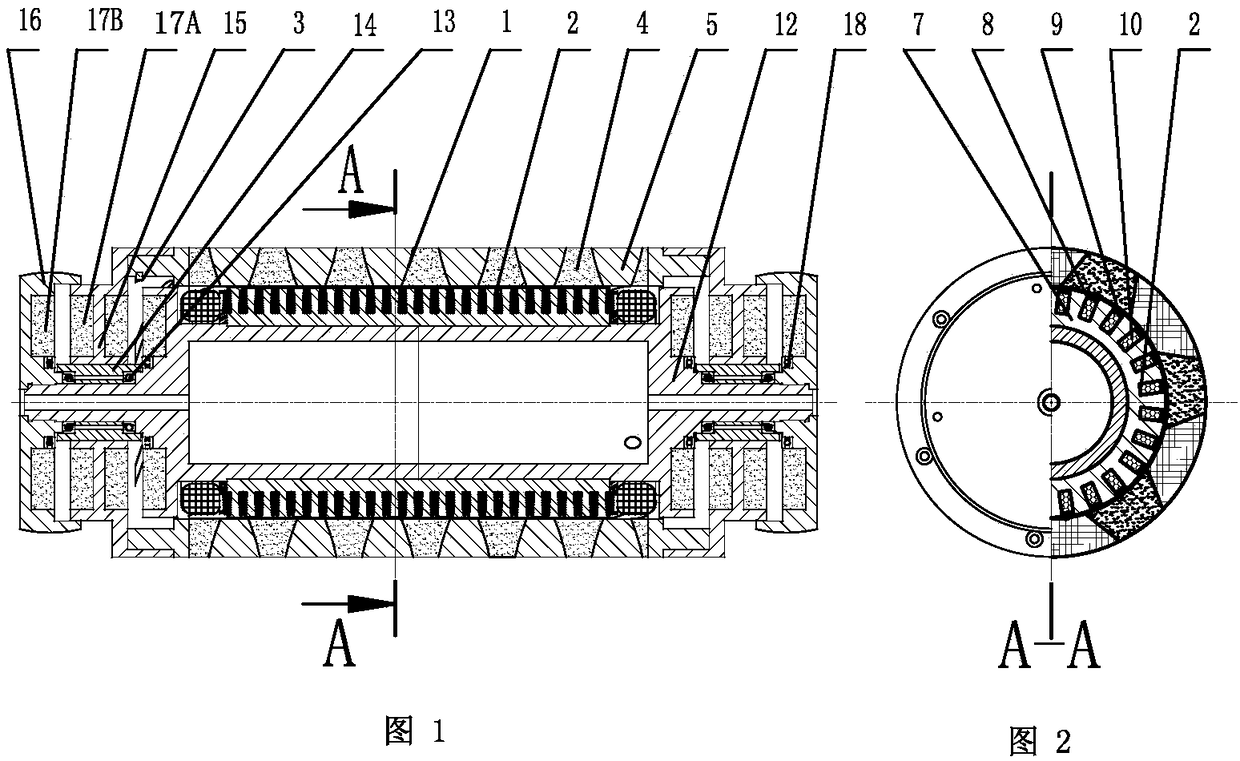
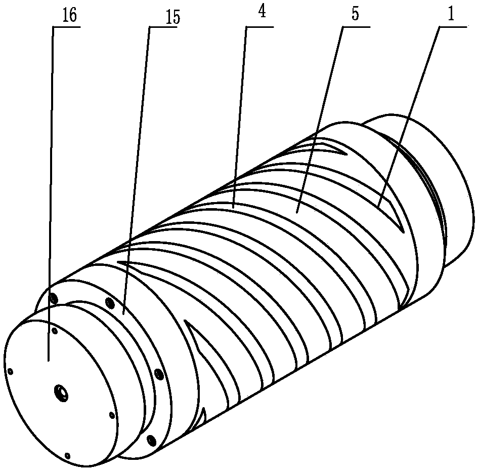
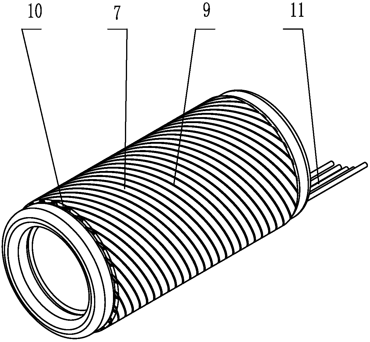
External helical rotor permanent magnet motor and permanent magnetic levitation wheel-rail vehicle system
A rotor motor and magnetic levitation technology, which is applied to synchronous motors with stationary armatures and rotating magnets, magnetic circuits, motor vehicles, etc., can solve the problems of low efficiency, reduce the weight of the whole machine, reduce the volume, and increase the driving force Effect
- Summary
- Abstract
- Description
- Claims
- Application Information
AI Technical Summary
Problems solved by technology
Method used
Image
Examples
Embodiment 1
[0108] Embodiment 1: permanent maglev wheel-rail subway train
[0109] Such as Figure 12 , Figure 13 As shown, two steel rails 35 are built on the concrete subgrade 34, and a groove 42 is opened downward at the central position of the two steel rails 35. The top and side walls of the groove 42 are provided with steel embedded parts 36, and on the embedded parts 36 Connecting bolts or bolt holes are set, and adjustment backing plates 37 are provided as required, and inclined surfaces are arranged on the adjustment backing plates 37, and the thickness can be adjusted by relative movement of the two adjustment backing plates 37. The driving system composed of the outer helical rotor linear permanent magnet driver 38 and the helical stator 32 is located at the central position of the two rails, the outer helical rotor permanent magnet motor 38 is coaxially arranged with the outer helical stator 32 with openings, the helical The thread stator 32 is provided with an opening up a...
Embodiment 2
[0116] Embodiment 2: permanent maglev highway and permanent maglev bus
[0117] Such as Figure 17 Shown, also can only lay this permanent maglev driving track 51 on the urban bus main road, and needn't lay two steel rails, become permanent maglev highway. That is, the outer helical rotor permanent magnet motor 38 is coaxially arranged with the helical stator 32 with openings on the outside, and the helical stator 32 penetrates up and down to become two semicircular helical stators 32, each helical stator 32 outside is A horizontal rib 39 and a vertical rib 40 are provided, and the horizontal rib 39 and the vertical rib 40 are L-shaped. A Z-shaped suspension plate 41 is arranged at the bottom of the helical stator 32 . The horizontal ribs 39 on the left and right sides of the helical stator 32 ride on the embedded parts 36 on the shoulders of the concave groove 42, and an adjusting backing plate 37 is arranged between the horizontal ribs 39 and the embedded parts 36, and the...
Embodiment 3
[0122] Example 3: Single-axis drive 4-channel permanent maglev elevated light rail
[0123] Such as Figure 18 As shown above, the support column 61 is erected on the green belt of the highway, the central line or the corridor on both sides of the road, or the support column 61 is erected on the line of urban planning. A crossbeam 62 is laid on the top of the column, and the crossbeam 62 can be on one side of the column, or the crossbar can stretch out to both sides on the column 61 . A longitudinal box girder 63 is erected on the side of the cross beam 62, and the longitudinal box girder 63 can be a reinforced concrete structure or a steel beam. The top of the longitudinal box girder 63 is connected to the helical stator 32 with openings. A transition beam 64 may also be provided between the longitudinal box girder 63 and the helical stator 32 to facilitate installation. The transition beam 64 is connected to the upper part of the longitudinal box beam 63 , and the bottom ...
PUM
 Abstract
Description
Claims
Application Information
 - R&D
- Intellectual Property
- Life Sciences
- Materials
- Tech Scout
- Unparalleled Data Quality
- Higher Quality Content
- 60% Fewer Hallucinations
Browse by: Latest US Patents, China's latest patents, Technical Efficacy Thesaurus, Application Domain, Technology Topic, Popular Technical Reports.
© 2025 PatSnap. All rights reserved.Legal|Privacy policy|Modern Slavery Act Transparency Statement|Sitemap|About US| Contact US: help@patsnap.com


