Droplet target control system guided by laser beam

A technology for controlling a system and a laser beam, applied in the field of plasma light sources, can solve the problem of high difficulty in realizing a drop target system, and achieve the effects of long-term accurate and stable spatial coincidence, slowing down the falling speed, and realizing time synchronization.

Active Publication Date: 2013-07-24
上海中科神光光电产业有限公司
View PDF5 Cites 16 Cited by
  • Summary
  • Abstract
  • Description
  • Claims
  • Application Information

AI Technical Summary

Problems solved by technology

In addition, the requirements for target size, shape uniformity, and high stability and consistency at high repetition rates make it very difficult to realize the droplet target system

Method used


Image

  • Droplet target control system guided by laser beam
  • Droplet target control system guided by laser beam

Examples


Embodiment Construction

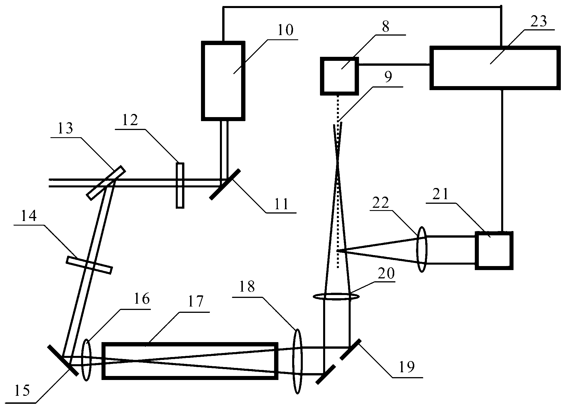
[0017] Such as figure 2 Shown is a schematic structural view of the laser beam guided droplet target control system of the present invention. As can be seen from the figure, the droplet target control system guided by the laser beam of the present invention includes a droplet nozzle 8, a high-power pump laser 21, a third focusing lens 22 and a delay pulse generator 23, and also includes a laser light source 10, a first Mirror 11, half-wave plate 12, Brewster’s angle polarizer 13, quarter-wave plate 14, second mirror 15, first focusing lens 16, vacuum tube 17, second focusing lens 18, annular plane reflector Mirror 19 and annular focusing lens 20, the positional relationship of the above-mentioned components is as follows: along the laser direction of the laser light source 10 output is the first reflector 11, half-wave plate 12, Brewster angle polarizer 13, four One-half wave plate 14, the second reflection mirror 15, the first focus lens 16, the vacuum tube 17, the second f...


PUM

PropertyMeasurementUnit
diameteraaaaaaaaaa

Abstract

The invention discloses a droplet target control system guided by a laser beam. The droplet target control system comprises a droplet nozzle, a high-power pump laser, a third focusing lens and a time delay pulse generator, and further comprises a laser source, a first reflector, a half valve plate, a Brewster angle polarizing film, a quarter wave plate, a second reflector, a first focusing lens, a vacuum tube, a second focusing lens, an annular plane reflector and an annular focusing lens. A dropping track of metal droplets in 20 micron dimension can be precisely controlled by the droplet target control system, and the dropping speed of the droplets can be regulated. The system is capable of stably working for a long time, the time synchronization and the space coincidence of the droplets and the high-power pump laser are guaranteed.

Description

technical field [0001] The invention relates to a plasma light source of an extreme ultraviolet lithography machine, in particular to a liquid drop target control system suitable for guiding a laser beam of a plasma light source of an extreme ultraviolet lithography machine. Background technique [0002] Lithography machines are key equipment for manufacturing large-scale integrated circuits. The lithography machine uses ultraviolet light (such as 193nm wavelength laser) to selectively remove the protective film on the surface of the semiconductor wafer according to the circuit diagram. The photolithographic semiconductor wafer can be formed into an integrated circuit after liquid corrosion and other treatments. The fineness of the integrated circuit depends on the size of the UV focused spot. According to the diffraction theory, the shorter wavelength of extreme ultraviolet light can obtain a smaller focused spot. The extreme ultraviolet lithography machine uses extreme ...

Claims


Application Information

Patent Timeline
Patent Type & Authority Applications(China)
IPC IPC(8): G03F7/20G02B27/09
Inventor 冷雨欣王乘赵全忠向世清李儒新
Owner 上海中科神光光电产业有限公司
Why Eureka
Try Eureka