Reverse-conducting insulated-gate bipolar transistor (RC-IGBT) with P floating layer current bolt

A floating layer and current technology, applied in the direction of circuits, electrical components, semiconductor devices, etc., can solve the problems of device reliability, increased turn-off loss, high local temperature, etc., to reduce the turn-off time, reduce the transition voltage, The effect of small cell size

Inactive Publication Date: 2013-07-24
UNIV OF ELECTRONICS SCI & TECH OF CHINA +1
View PDF1 Cites 27 Cited by
  • Summary
  • Abstract
  • Description
  • Claims
  • Application Information

AI Technical Summary

Problems solved by technology

However, this traditional RC-IGBT will have a negative resistance effect (snapback) when it is conducting forward conduction, and the uneven current will cause the local temperature to be too high, so there are reliability problems.
Later, in order to solve the snapback phenomenon, M. Rahimo and others invented BIGT (Bi-mode Insulated Gate Transistor, dual-mode insulated gate bipolar transistor), such as figure 2 As shown, on the basis of the traditional RC-IGBT, the device solves the snapback phenomenon by enlarging the original cell area and dividing it into the IGBT part and the RC-IGBT part. To completely eliminate the snapback requires more than 2500μm), which will increase the turn-off loss, and because the hole emission efficiency of the two parts is different, the current concentration phenomenon will be more prominent, which will further cause the local temperature to be too high, which will affect the reliability of the device. cause serious impact

Method used


Image

  • Reverse-conducting insulated-gate bipolar transistor (RC-IGBT) with P floating layer current bolt
  • Reverse-conducting insulated-gate bipolar transistor (RC-IGBT) with P floating layer current bolt
  • Reverse-conducting insulated-gate bipolar transistor (RC-IGBT) with P floating layer current bolt

Examples


Embodiment Construction

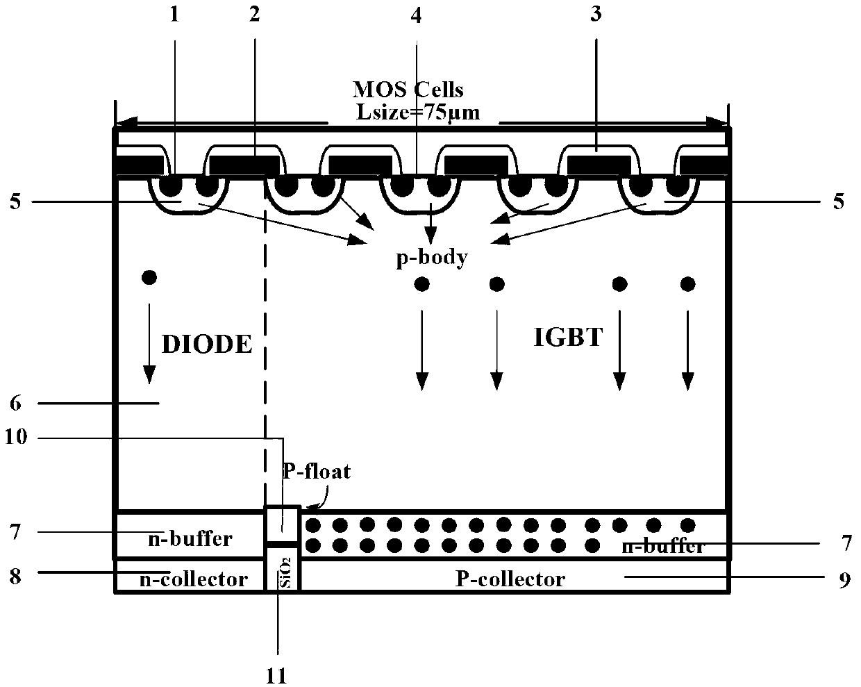
[0030] A kind of RC-IGBT with P floating layer proposed by the present invention, its structure is as follows image 3 As shown, it includes N+ active region 1, polysilicon gate electrode 2, silicon dioxide layer 3, active emitter 4, body P region 5, N-drift region 6, P floating layer current plug 7, N buffer layer 8 , N collector region 9, P collector region 10, silicon dioxide buried layer 11, N collector region and P collector region are located on both sides of the silicon dioxide buried layer 11, and the P floating layer 7 is located on the silicon dioxide buried layer Above the layer 11, the N buffer layer 8 is located above the N collector region 9 and the P collector region 10 and distributed on both sides of the P floating layer 7, and the N-drift region 6 is located on the N buffer layer 8 and the P floating layer. 7, the body P region 5 is located below the active emitter 4 and connected to the emitter 4, the N+ active region 1 is located inside the body P region 5 ...


PUM


Abstract

The invention discloses a reverse-conducting insulated-gate bipolar transistor (RC-IGBT) with a P floating layer current bolt, and belongs to the field of semiconductor power elements. A medium buried layer is led in between an N collector region and a P collector region of a traditional RC-IGBT, and the P floating layer current bolt is led into an N-type buffering layer above the medium buried layer. According to the RC-IGBT with the P floating layer current bolt, other parameters of an element are not affected, break-over voltage of a snapback is obviously lowered, a reverse recovery soft factor is improved, current is distributed uniformly, local over-heating phenomenon is avoided, and the reliability of the RC-IGBT is improved.

Description

technical field [0001] An RC-IGBT (reverse-conducting insulated-gate bipolar transistor, reverse conducting insulated gate bipolar transistor) with a P floating layer current plug belongs to the field of semiconductor power devices. Background technique [0002] IGBT (Insulate Gate Bipolar Transistor, Insulated Gate Bipolar Transistor) not only has the advantages of high input impedance, low control power, simple drive circuit, and high switching speed of MOSFET, but also has the advantages of high current density and saturation voltage of bipolar power transistor. It has the advantages of low power consumption and strong current handling ability, so it is widely used in induction cooker, UPS uninterruptible power supply, automotive electronic igniter, three-phase motor inverter, welding machine switching power supply and other products as power switch tube or power output tube, the market prospect very broad. IGBT products are very ideal switching devices in the field of p...

Claims


Application Information

Patent Timeline
Patent Type & Authority Applications(China)
IPC IPC(8): H01L29/739H01L29/06
Inventor 李泽宏陈伟中刘永任敏张波
Owner UNIV OF ELECTRONICS SCI & TECH OF CHINA
Why Eureka
Try Eureka