
Solid oxide fuel cell system and thermoelectricity synergic control method

A fuel cell system and solid oxide technology, which is applied in solid electrolyte fuel cells, fuel cells, fuel cell additives, etc., can solve the problems of high exhaust gas temperature, limited adjustable flow, not considering SOFC system, etc., to improve the system. Efficiency and guaranteed service life

Active Publication Date: 2013-08-07
武汉华科福赛新能源有限责任公司
View PDF10 Cites 42 Cited by
  • Summary
  • Abstract
  • Description
  • Claims
  • Application Information

AI Technical Summary

Problems solved by technology

U.S. patents US6608463B1 and US7001682B2 disclose a relatively complete SOFC system, which has a stack unit, an air supply unit, a fuel supply unit, and an exhaust gas recovery unit, but the system has the following defects: 1) Independent start-up combustion chamber And the exhaust combustion chamber, start the combustion chamber to preheat the system, this design increases the system components, increases the volume, and increases the cost and control complexity
2) The system adjusts the temperature by adjusting the gas flow at the cathode inlet of the stack entering the exhaust gas combustion chamber, which requires the system to provide a regulating valve that can withstand high temperatures above 800°C to control the flow, so the system requires expensive high-temperature regulating valves, which increases the cost
Moreover, due to the high temperature of the cathode tail gas of the stack and the limited adjustable flow rate, the control effect on the temperature of the tail gas combustion chamber is not good.
3) The flue gas from the exhaust gas combustion chamber preheats the air and the temperature after the reformer may only be 300-400°C, and then it is passed into the electric stack for preheating, which will cause two problems. a. The working temperature of the electric stack is generally 600-600 900°C, the temperature of the exhaust gas discharged from the system may be very high, b. The exhaust gas temperature of the preheating stack is too low, which will cause the working temperature of the stack to drop
Chinese patents CN1685552A, CN1151575C, CN100342578C and U.S. patent US7056611B2 do not consider a complete SOFC system, and cannot guarantee efficient and long-life operation of the stack

Method used


Image

  • Solid oxide fuel cell system and thermoelectricity synergic control method
  • Solid oxide fuel cell system and thermoelectricity synergic control method

Examples


Embodiment Construction

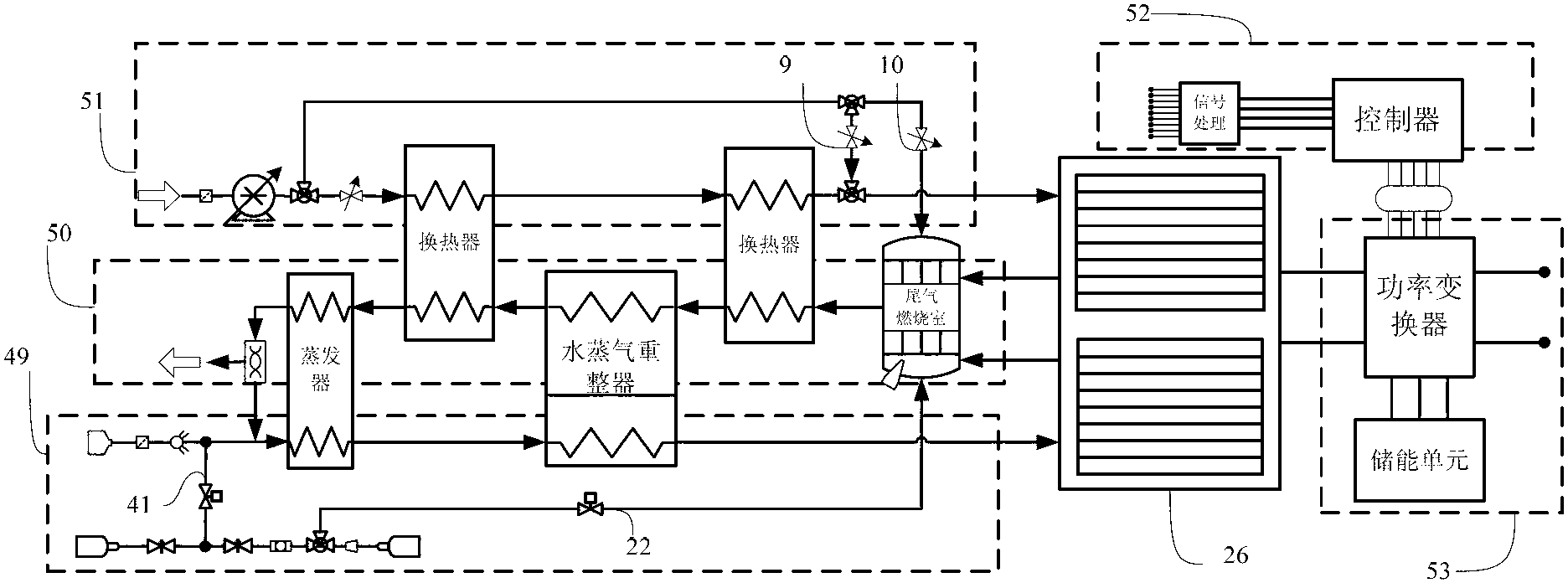
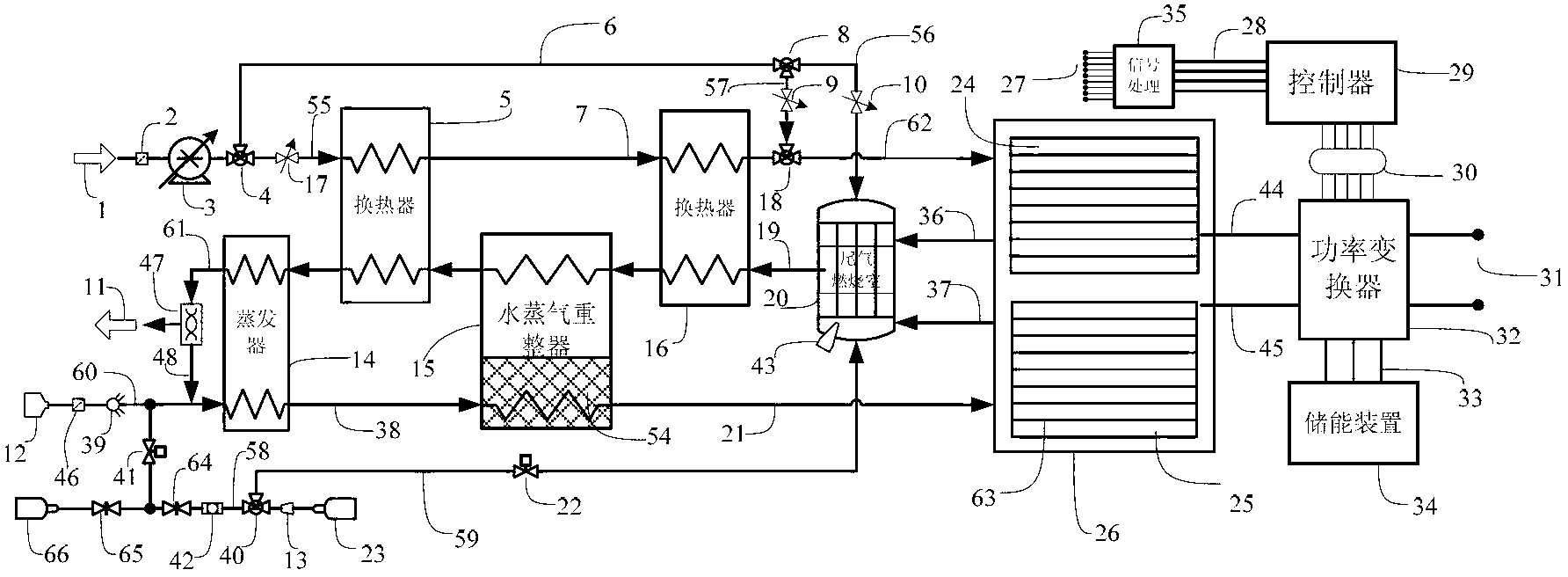
[0034] like figure 1 As shown, the system includes: stack unit 26, air supply unit 51, fuel supply unit 49, exhaust gas recovery unit 50, electrical management unit 52, control unit 53, first valve 9, second valve 10, first mass flow meter 22 and the second mass flow meter 41. The first output end of the air supply unit 51 is connected to the cathode gas input end of the stack unit 26 through the first valve 9 pipeline, and the second output end of the air supply unit 51 is connected to the air input end of the tail gas recovery unit 50 through the second valve 10 pipeline The hydrogen output end of the fuel supply unit 49 is connected to the anode gas input end of the stack unit 26 by the second mass flow meter 41 pipelines, and the fuel output end of the fuel supply unit 49 is connected to the tail gas recovery unit 50 by the first mass flow meter 22 pipelines Fuel input end; the exhaust gas output end of the electric stack unit 26 is connected to the input end of the exhau...


PUM


Abstract

The present invention discloses a solid oxide fuel cell system and a control method thereof, and belongs to the field of fuel cells. According to the solid oxide fuel cell system structure, an output end of an air supply unit is connected with an input end of a stack unit through a valve, and is connected with an input end of a tail gas recovery unit through a valve, an output end of a fuel supply unit is connected with the input end of the stack unit through a mass flow meter, and is connected with the input end of the tail gas recovery unit through a mass flow meter, an output end of the stack unit is connected with the input end of the tail gas recovery unit, an output end of the tail gas recovery unit is connected with an input end of the fuel supply unit, and a control unit is respectively connected with various valves, various mass flow meters and various units. According to the present invention, work states of various valves and various flow meters are coordinatedly controlled according to load power requirements, and work temperatures of various units are regulated through adjusting gas flows so as to complete thermal-electric system control, improve system efficiency, and ensure a service life of the stack.

Description

technical field [0001] The invention belongs to the field of fuel cells, in particular, it is a solid oxide fuel cell thermoelectric coordinated control system and method. Background technique [0002] Solid oxide fuel cells (SOFC) can directly convert chemical energy into electrical energy through electrochemical reactions. Since the power generation process is not subject to the thermodynamic limitations of the Carnot cycle, there is no mechanical vibration, and hydrogen is mainly used as fuel, it has high power generation efficiency. With the advantages of quietness, no noise, environmental friendliness and low emission, it is the most promising green power generation system in the 21st century. In the past ten years, many developed countries in the world, such as the United States, Germany, and Japan, have invested a lot of money and manpower in the development of SOFC systems, promoting the development of SOFC technology, and the goal is to achieve commercialization. Ho...

Claims


Application Information

Patent Timeline
IPC IPC(8): H01M8/04H01M8/12H01M8/04746H01M8/1231
CPCY02E60/521Y02E60/525Y02E60/50
Inventor 李曦蒋建华邓忠华李箭蒲健池波杨杰
Owner 武汉华科福赛新能源有限责任公司
Learn More