
Method for machining variable-section nozzle ring blade of turbocharger
A turbocharger and processing method technology, applied in metal processing equipment, machine tools suitable for grinding workpiece planes, manufacturing tools, etc., can solve the problems of difficulty in guaranteeing the mechanical properties of parts, difficulty in processing quality control, and high processing scrap rate, etc. problem, to achieve the effect of low processing cost, low surface roughness and low production cost
- Summary
- Abstract
- Description
- Claims
- Application Information
AI Technical Summary
Problems solved by technology
Method used
Image

Examples
Embodiment Construction
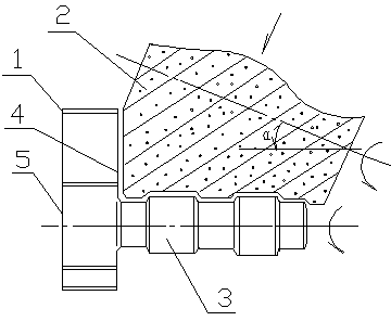
[0013] The method for processing the turbocharger variable cross-section nozzle ring blades of the present invention is: clamping and fixing the blade 1 (that is, the turbocharger variable cross-section nozzle ring blades) on the fixture of the power shaft of the machine tool, and according to the process It is required to perform a uniform rotating motion at a certain speed. According to the shape and size of the blade, the corresponding outer contour shape of the grinding wheel is produced, and the ratio of the feed width to the feed depth of the grinding wheel is obtained. According to the ratio of the feed width to the feed depth (Trigonometric function value) Calculate the feed angle and displacement of the grinding wheel 2, input the feed angle and displacement into the computer, and through computer control, the grinding wheel is rotated at a constant speed while relative to the blade to make the grinding wheel according to the feed angle (such as figure 1 As shown in α)...
PUM
 Abstract
Description
Claims
Application Information