Molding method of unidirectional reinforced composite material with carbon nanotubes perpendicular to fiber direction

A fiber-oriented and unidirectional reinforcement technology, applied in the field of materials and fiber-reinforced composite materials, can solve the problems of low strength, weak bearing capacity and small elongation, and achieve the effect of quick effect, easy control and high degree of orientation

Inactive Publication Date: 2013-09-11
NO 53 RES INST OF CHINA NORTH IND GRP
View PDF5 Cites 9 Cited by
  • Summary
  • Abstract
  • Description
  • Claims
  • Application Information

AI Technical Summary

Problems solved by technology

[0006] The purpose of the present invention is to provide a carbon nanotube reinforced unidirectional prepreg molding method perpendicular to the fiber direction, so as t

Method used


Image

  • Molding method of unidirectional reinforced composite material with carbon nanotubes perpendicular to fiber direction
  • Molding method of unidirectional reinforced composite material with carbon nanotubes perpendicular to fiber direction

Examples


Embodiment 1

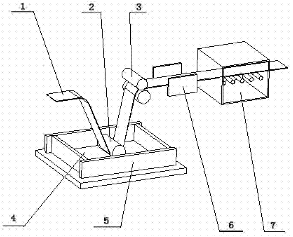
[0020] The technical scheme involved in the invention is described by taking the double-oriented CNTs / T700 carbon fiber reinforced epoxy unidirectional prepreg prepared by a winding machine equipped with drying equipment and a model of 4FW500 as an example. The structure of the orientation device is as follows: figure 2 shown.

[0021] A polytetrafluoroethylene rubber tank is used, and a DC electric field A is set in the rubber tank 4. The electric field A is composed of a pair of electrodes 5, the electrode area is 100mm×115mm, and the electrode distance is 100mm; the rubber roller 2 is placed in the electric field, and the axis direction of the rubber roller core is in line with The direction of the electric field is parallel, and the center of gravity of the rubber roller is located in the center between the two electrodes.

[0022] Set a DC electric field B at 200mm behind the squeeze roller 3 (between the squeeze roller 3 and the drying chamber 7). The electric field B i...

Embodiment 2

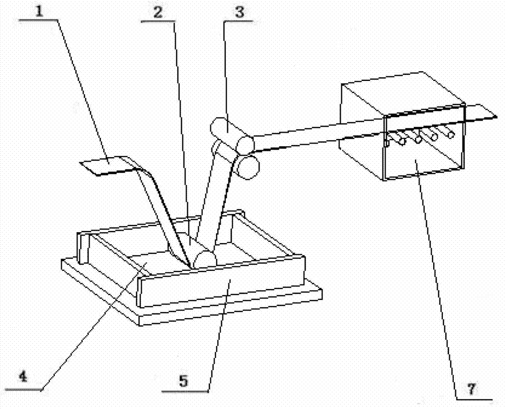
[0026] Taking the preparation of oriented CNTs-E glass fiber reinforced polyester unidirectional prepreg tape with drying equipment and model SKLCI50 / 500 winding machine as an example, the technical scheme involved in the invention is explained. The structure of the orientation device is as follows: figure 1 shown.

[0027] A ceramic glue tank 4 is used, and a direct current electric field A is set in the glue tank. The direct current electric field A is composed of a pair of electrodes 5, the electrode area is 415 mm long x 400 mm high, and the electrode distance is 400 mm; the rubber roller 2 is placed in the electric field, and the axis direction of the rubber roller core is in line The direction of the electric field is parallel, and the center of gravity of the rubber roller is located in the center between the two electrodes.

[0028] The glue is polyester resin system, solid 184 polyester, solid 199 polyester, diisophenyl peroxide DPO, dipropylene phthalate DAP, benzoyl...

Embodiment 3

[0031] Taking the preparation of oriented CNTs-S glass fiber reinforced polyester unidirectional prepreg tape with a set of drying equipment and model SKLCI50 / 500 winding machine as an example, the technical scheme involved in the invention is explained. The structure of the orientation device is as attached figure 1 shown.

[0032] A ceramic glue tank is used, and a DC electric field A is set in the glue tank 4. The electric field A is composed of a pair of electrodes 5. The electrode area is 415mm long × 400mm high, and the electrode distance is 400mm; The directions are parallel, and the center of gravity of the rubber roller is located in the center between the two electrodes.

[0033] The glue is an epoxy resin system, and the mass ratio of E20 epoxy resin, DDS, boron trifluoride monoethylamine, acetone, and acid-treated, amine-functionalized carbon nanotubes is 60:8:1:70:2. After mixing the resin according to a conventional method, stir it magnetically for 40 minutes an...


PUM

PropertyMeasurementUnit
Electric field strengthaaaaaaaaaa
Modulusaaaaaaaaaa

Abstract

The invention belongs to the technical field of materials, relates to the technical field of fiber reinforced composite materials, and particularly relates to a molding method of a unidirectional reinforced composite material with carbon nanotubes perpendicular to a fiber direction. The molding method comprises the working procedures of glue solution preparation, nanotube orientation, glue dipping, winding and molding. The orderly arrangement of the carbon nanotubes (CNTs) in a glue solution is realized by applying a direct-current electric field to the CNTs dispersed in resin, and a direct-current electric field is applied again between an extrusion roller and a drying chamber to perform secondary orientation on the CNTs dipped on the surface of fiber bundles, so that the orientation degree of the CNTs in the composite material is high, and the interlayer mechanical properties and the electrical conductivity are substantially improved. The molding method of the unidirectional reinforced composite material with the carbon nanotubes perpendicular to the fiber direction provided by the invention is easy to operate and control, low in requirements on equipment transformation, less in investment, quick in effect, widely applicable to winding systems with a semi-dry process, and especially applicable to the molding of unidirectional prepregs and composite materials thereof.

Description

technical field [0001] The invention belongs to the technical field of materials, relates to the technical field of fiber-reinforced composite materials, and in particular relates to the processing technology of directional carbon nanotube reinforced unidirectional prepreg. Background technique [0002] The fibers of fiber-reinforced resin-based unidirectional composites are restricted by the properties of the resin matrix and the fiber-resin interface. Compared with the fiber direction, there is a large gap in performance, which becomes the most common cause of composite damage on the microscopic level. Macroscopically, the interlayer strength of composite materials is low, the impact damage tolerance is small, and the thermal performance is poor. This has greatly restricted the design and application of composite materials, which has affected the advantages of composite materials. For unidirectional prepreg, like the unidirectional composite material prepared from it, the...

Claims


Application Information

Patent Timeline
IPC IPC(8): B29C70/50B29C70/54
Inventor 王丹勇陈以蔚郑志才李树虎秦贞明魏化震徐井利
Owner NO 53 RES INST OF CHINA NORTH IND GRP
Why Eureka
Try Eureka