Aircraft turbine blade laser shock method and device

A technology of aircraft turbine blades and laser shock, which is applied in the direction of heat treatment equipment, furnaces, heat treatment furnaces, etc., can solve the problems of easy deformation, poor strengthening effect, difficult laser shock on the curved surface of aircraft turbine blades, etc., and achieve the effect of improving strength

Active Publication Date: 2014-07-30
JIANGSU UNIV
View PDF4 Cites 4 Cited by
  • Summary
  • Abstract
  • Description
  • Claims
  • Application Information

AI Technical Summary

Problems solved by technology

[0005] The object of the present invention is to provide a method and device for laser shocking aircraft turbine blades, in order to solve the problem that the curved surface of aircraft turbine blades is difficult to perform laser shock and easy to deform, and prevent the surface of aircraft turbine blades from being damaged due to the use of a single laser process parameter. Poor strengthening effect

Method used


Image

  • Aircraft turbine blade laser shock method and device
  • Aircraft turbine blade laser shock method and device

Examples


Embodiment 1

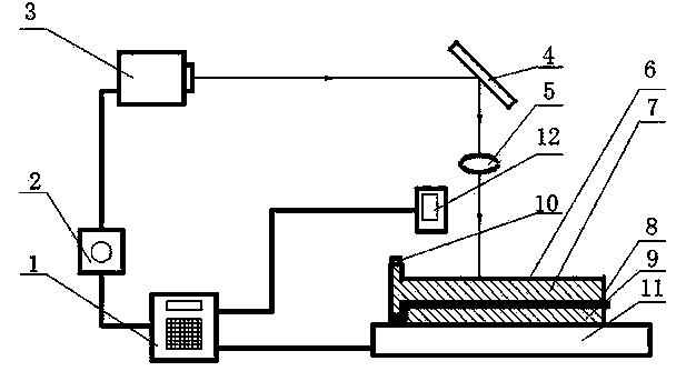
[0026] The device for laser impacting aircraft turbine blades of the present invention includes: high-power pulse laser 3, flexible film 6, aircraft turbine blades 7, gasket 8, die 9, three-axis numerical control workbench 11, computer control system 1, thickness measuring device 12. The laser system consists of a laser power supply 2, a high-power pulse laser 3, a 45° total reflection mirror 4, and a transmission mirror 5. The clamping seat 10 is used for clamping the tenon of the aircraft turbine blade 7 to ensure that the aircraft turbine blade 7 and the die 9 fit closely. The clamping device 10 is fixed on the three-axis numerical control workbench 11, and the flexible film 6 is the constraining layer and the absorbing layer. The computer control device 1 controls the three-axis numerically controlled workbench 11, the high-power pulse laser 3 and the thickness measuring device 12, and impacts by area until the target surface of the entire aircraft turbine blade 7 is proc...

Embodiment 2

[0028] The specific steps of implementing a method for laser shock strengthening aircraft turbine blades are:

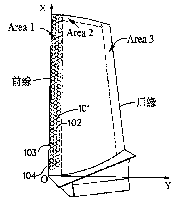
[0029] (1) Use UG, PRO / E and other three-dimensional software to carry out the solid modeling of the aircraft turbine blade 7. The aircraft turbine blade is made of IN853 nickel-based superalloy, and the maximum thickness of the aircraft turbine blade 7 is 2 mm. The thinnest area between the leading edge and the trailing edge 0.25mm, the die 9 is processed, and the die 9 is polished and deburred;

[0030] (2) The die 9 is placed on the three-axis numerical control workbench 11, and then a 0.5mm flexible gasket 8 is placed on the die, and then the aircraft turbine blade 7 is placed on the top of the flexible gasket 8 to ensure that the aircraft turbine blade 7. The flexible gasket 8 and the die 9 are tightly fitted, and finally the tenon of the aircraft turbine blade 7 is fixed by the clamping device 10;

[0031] (4) the 0.1mm thick flexible film 6 is adhered to the ...

Embodiment 3

[0038] Change the parameters of the high-power pulsed laser 3 in Example 2 to laser energy and power density as shown in Table 3 below, the spot radius is 1.5mm and the laser pulse width is 12ns, the flexible spacer is 0.8mm, and other methods and steps remain unchanged .

[0039] Table 2 Corresponding value of blade impact point thickness and laser energy and power density

[0040] Thickness (mm) Energy (J) Power density (GW / cm 2 ) 0.27 2.48 2.93 0.40 3.67 4.33 0.48 4.41 5.20 0.56 5.14 6.06


PUM

PropertyMeasurementUnit
thicknessaaaaaaaaaa
radiusaaaaaaaaaa
widthaaaaaaaaaa

Abstract

The invention discloses a method and a device for laser shocking aircraft turbine blades. Firstly, a die and a flexible pad are used to support the back of the aircraft turbine blade, and secondly, a thickness measuring device is used to measure the thickness corresponding to each point of the aircraft turbine blade. , thickness, and laser shock strengthening parameters, determine the laser process parameters required for each point of the aircraft turbine blade, and finally realize the laser shock strengthening of the entire surface of the aircraft turbine blade according to the above laser process parameters for each point of the aircraft turbine blade. The device for implementing the method includes a high-power pulsed laser, an aircraft turbine blade, a flexible gasket, a die, a three-axis numerical control workbench, a computer control system, and a thickness measuring device. The invention can prevent deformation and cracking of aircraft turbine blades and obtain uniform residual compressive stress distribution, is suitable for strengthening aircraft turbine blades with complex curved surfaces and uneven thicknesses, and can also be extended to laser shock strengthening of steam turbine and water turbine blades.

Description

technical field [0001] The invention relates to the technical field of laser processing, in particular to a laser shock strengthening technology. Background technique [0002] Shot peening is a process that improves the properties of metallic materials. Traditional shot peening usually uses mechanical methods, such as hammering or shooting, to cause plastic deformation of the metal surface, thus generating residual compressive stress on the surface of the workpiece. However, mechanical shot peening will cause the surface of the workpiece to become rough, so that the fatigue resistance and corrosion resistance of the workpiece cannot be well improved. However, using laser pulses instead of marbles as a peening tool can better impact the metal surface. Usually in laser shock peening, an opaque coating such as black paint or aluminum foil is attached to the metal surface to absorb laser energy to generate plasma, and a layer is added on top of the absorbing layer. The transp...

Claims


Application Information

Patent Timeline
Patent Type & Authority Patents(China)
IPC IPC(8): C21D1/09C21D9/00
Inventor 鲁金忠齐晗罗密王志龙
Owner JIANGSU UNIV
Why Eureka
Try Eureka