Secondary optical lens of LED backlight system for flat liquid crystal display

A secondary optical lens and liquid crystal display technology, which is applied in optics, lenses, optical components, etc., can solve problems such as spot black shadows, unreasonable light distribution methods, and light energy loss, and achieve the effect of reducing light energy loss

Inactive Publication Date: 2013-09-25
MIKOLTA OPTICAL TECH CO
View PDF6 Cites 18 Cited by
  • Summary
  • Abstract
  • Description
  • Claims
  • Application Information

AI Technical Summary

Problems solved by technology

However, the method of light distribution is unreasonable. According to the rule that "the increase of θ5 is greater than the increase of θ1 (Δθ5 / Δθ1)", when the angle θ1 between the incident light of the lens and the optical axis is 90° , the angle θ5 between the outgoing light and the optical axis will exceed 90°, so that it will shoot to the rear of the lens and hit the PCB board, resulting in loss of light energy
In addition, when the concave incident surface below the lens is relatively steep, this light distribution method will cause a black shadow in the center of the spot

Method used


Image

  • Secondary optical lens of LED backlight system for flat liquid crystal display
  • Secondary optical lens of LED backlight system for flat liquid crystal display
  • Secondary optical lens of LED backlight system for flat liquid crystal display

Examples


no. 1 Embodiment approach

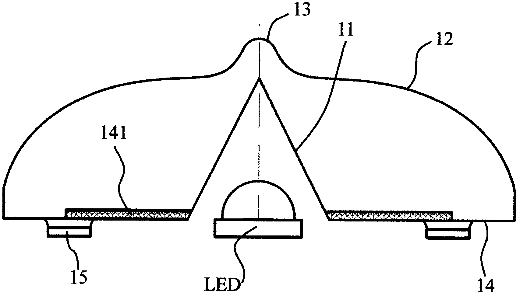
[0052] Such as figure 1 Shown, it is the first specific embodiment of the secondary optical lens of the LED backlight system that the present invention is used for flat liquid crystal display, and the central part of this optical lens bottom has a conical inner concave surface 11, and it is incident surface; Lens There is a flat light distribution curved surface 12 on the top of the lens, which is an exit surface, and it is a continuous smooth curved surface; there is an obvious protrusion 13 at the center of the curved surface 12 on the top of the lens, and the protrusion is arc-shaped; the bottom surface of the lens 14 It is a non-optical surface, on which there is a corner cube prism type retro-reflective microstructure surface 141 for collecting stray light; the so-called corner cube prism refers to an angle cut off from a regular cube, and its three faces are all perpendicular to each other. So it is called a corner cube; a microstructure array formed by arranging the mi...

no. 2 Embodiment approach

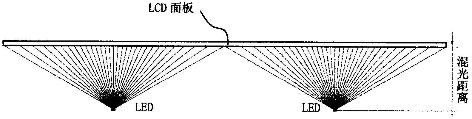
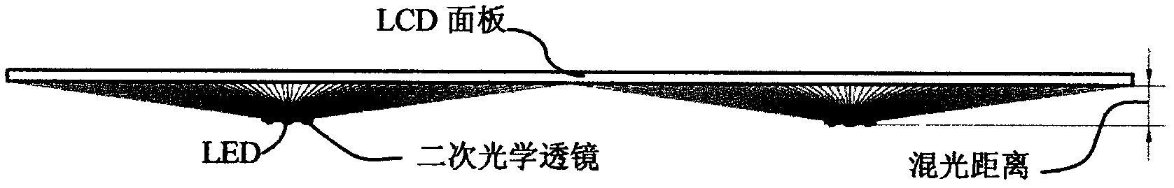
[0084] When the phosphor powder of the LED chip is coated relatively thinly and the coating area is relatively large, the secondary optical lens described in the first specific embodiment is used to distribute the light emitted by the LED. Since the light distribution angle is very large, it is possible On the screen, there will be inconsistencies such as high color temperature in the center of the light spot and low color temperature at the edge of the light spot, resulting in poor color uniformity of the LCD panel. The second specific embodiment described in the present invention proposes a solution to this situation.

[0085] The sectional view of the second specific embodiment is as Figure 14As shown, except for the outer light distribution curved surface 22, all other features are the same as the first specific embodiment. Here, the outer light distribution curved surface 22 is designed as a diffractive surface with ring microstructures, so that the outgoing light surrou...


PUM

PropertyMeasurementUnit
beam angleaaaaaaaaaa

Abstract

The invention discloses a secondary optical lens of an LED (Light Emitting Diode) backlight system for flat liquid crystal display. The secondary optical lens comprises a light distribution curved surface used as an exit surface and a bottom surface positioned at the bottom of the light distribution curved surface, an inner concave surface of the incident surface is formed by concaving upwards from the bottom surface, and an upward projected bulge is formed in the center of the top part of the light distribution curved surface, so that the full beam angle of the secondary optical lens to be larger than or equal to 160 degrees, and the incident light can pass through the concave surface and the light distribution curved surface and then to be shot. The secondary optical lens is provided with a beam angle larger than 160 degrees, and can shoot most of the light of the LED in the side surface direction of the optical lens, the direction of the maximum light intensity is above a position where an angle of plus or minus 80 degrees is formed with the optical axis, uniformly distributed light with the same range can be generated on the LCD (Liquid Crystal Display) panel by adopting a very short mixing light distance, the mixing light distance can be decreased below one third of that of the prior art, and light energy loss can be decreased effectively.

Description

technical field [0001] The invention relates to a secondary optical lens used for an LED backlight system of a flat liquid crystal display. Background technique [0002] Because LED has the characteristics of high efficiency, energy saving, high brightness, and good color rendering index, most of the existing backlight systems of flat liquid crystal displays have adopted LED lighting technology (that is, light-emitting diode semiconductor solid-state lighting technology). The direct lighting method is highly praised by many manufacturers because of its features such as less light loss, high uniformity, free arrangement of LEDs, and no need for complicated light guide plate dot design. However, if the high-power Lambertian distribution (Lambertian) LED on the market is directly used, since its beam angle is only 120 degrees, the central light intensity is relatively strong, and a large light mixing distance is required to display it on the LCD (liquid crystal) screen. Produc...

Claims


Application Information

Patent Timeline
Patent Type & Authority Applications(China)
IPC IPC(8): F21V5/04G02F1/13357G02B3/00F21Y101/02
Inventor 郎欢标
Owner MIKOLTA OPTICAL TECH CO
Why Eureka
Try Eureka