Wide-range optical fiber vacuum sensor with multiple steps and manufacturing method thereof

A vacuum sensor and sensor technology, used in vacuum gauges, instruments, measuring devices, etc., can solve the problem that pressure sensors cannot be distinguished, and achieve the effect of ensuring the accuracy of diaphragm deformation measurement, reducing costs, and expanding the range of high-precision pressure measurement

Active Publication Date: 2013-10-09
TIANJIN UNIV
View PDF9 Cites 15 Cited by
  • Summary
  • Abstract
  • Description
  • Claims
  • Application Information

AI Technical Summary

Problems solved by technology

[0004] However, at present, the optical fiber Fabry-Perot sensor is mainly suitable for the detection of relatively large pressure measurement, usually greater than 100kPa. distinguish

Method used


Image

  • Wide-range optical fiber vacuum sensor with multiple steps and manufacturing method thereof
  • Wide-range optical fiber vacuum sensor with multiple steps and manufacturing method thereof
  • Wide-range optical fiber vacuum sensor with multiple steps and manufacturing method thereof

Examples


Embodiment 2

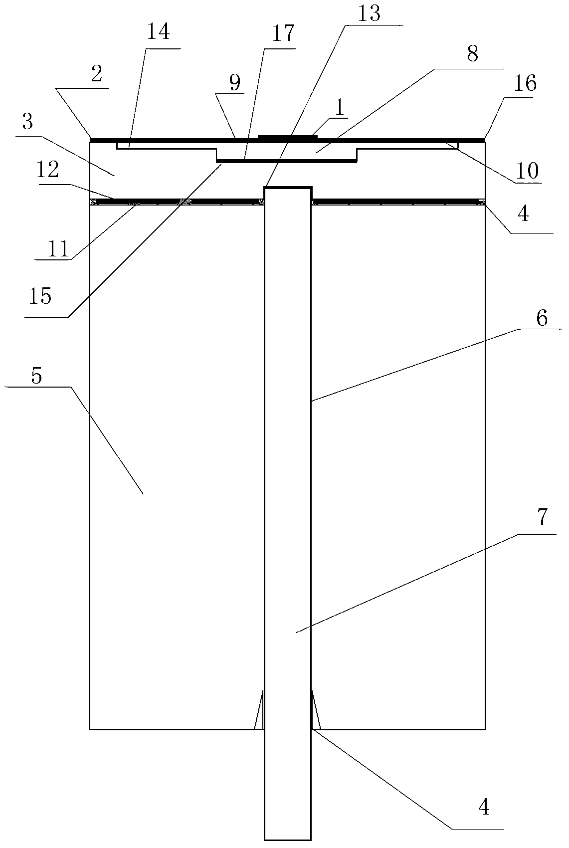
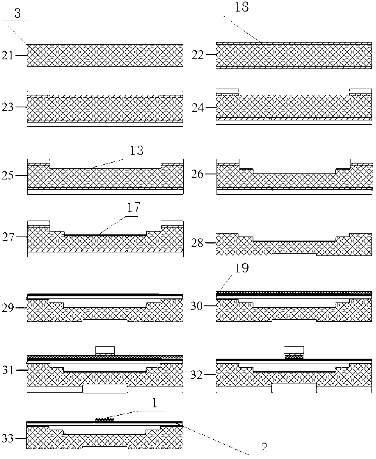
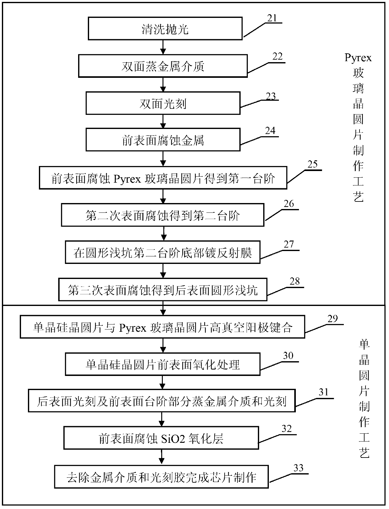
[0048] Embodiment 2: The specific implementation plan of batch production of optical fiber vacuum sensor sensing head by using 4-inch wafer

[0049] The first step 14 of the circular shallow pit array is etched on the front surface of the Pyrex glass wafer 3. The depth of the first step 14 of the circular shallow pit array is 1 μm to 5 μm, and the diameter is 1200 μm to 1900 μm. The pitch of the first step 14 array is 2500 μm; and then it is etched for the second time, and the second step 15 of the circular shallow pit array with a diameter of 500 μm to 800 μm and a depth of 20 μm to 40 μm from the first step 14 is etched out, At the same time, a reflective film 17 with a reflectivity of 10% to 50% is plated on the bottom of the step 15 as the first reflective surface of the Fabry-Perot cavity; after that, the rear surface of the Pyrex glass wafer 3 is etched for the third time, A circular shallow pit with a diameter of 180 μm to 300 μm and a depth of 30 μm to 40 μm is etched ...

Embodiment 3

[0050] Example 3: Optical fiber vacuum sensor step pressure sensing diaphragm disturbance deformation

[0051] Figure 4 For monocrystalline silicon wafers with SiO 2 Schematic diagram of the pressure-sensing diaphragm structure of the oxide layer step. When the external pressure changes, the pressure sensing diaphragm in the sensor head will be disturbed, with a certain amount of disturbance, and the corresponding disturbance amount can be obtained from the disturbance differential equation of the diaphragm:

[0052] w 1 = P ( r 4 64 D 1 - b 2 32 D 1 r 2 ...

Embodiment 4

[0063] Embodiment 4: Demodulation of fiber optic vacuum sensor

[0064] Optical fiber vacuum sensor demodulation system based on white light interference demodulation such as Figure 8 shown. The demodulation process is: the light emitted by the broadband light source 34 (the broadband light source includes white light LED, xenon lamp or halogen lamp) is coupled into the transmission fiber 7, and enters a 2×2 3dB coupler 35, and passes through the fiber 7 from the other end The other output terminal of the 2×2 3dB coupler 35 is connected to the matching liquid for transmission to the sensor 37 . The light signal reflected by the sensor 37 passes through the 2×2 3dB coupler again and then enters the demodulation system 36 to obtain a cavity length demodulation signal. The cavity length information of the fiber optic vacuum sensor can be obtained by calculating the peak position of the spectral envelope. Through the corresponding relationship between the external pressure and...


PUM

PropertyMeasurementUnit
diameteraaaaaaaaaa
depthaaaaaaaaaa
thicknessaaaaaaaaaa

Abstract

The invention discloses a wide-range optical fiber vacuum sensor with multiple steps and a manufacturing method of the wide-range optical fiber vacuum sensor with the multiple steps. The wide-range optical fiber vacuum sensor comprises a sensor head, a sensor body, a transmission optical fiber, a supporting structure of the sensor and an accommodating structure of the transmission optical fiber. The sensor head is a stepped optical fiber vacuum sensor head and provided with a dual-layer structure with SiO2 oxide layer steps. The first layer structure is a monocrystalline silicon wafer, the second layer structure is a Pyrex glass wafer, a two-level stepped round shallow pit array is arranged on the front surface of the Pyres glass wafer, the Pyres glass wafer is divided into single sensor units, wherein the surfaces of the sensor units are squares or other polygons, and the round shallow pit array comprises a first round shallow pit step and a second round shallow pit step. The wide-range optical fiber vacuum sensor achieves high precision pressure measurement in a vacuum region, can survive in a constant pressure range without other packaging measures, can be used for high precision measurement in the constant pressure range, can effectively expand the high precision pressure measurement range of the sensor, and is convenient to manufacture in a massive mode.

Description

technical field [0001] The invention relates to the technical field of an optical fiber pressure sensor. The sensor is used for detecting the degree of vacuum, and is also suitable for the detection of relative pressure and absolute pressure of liquids, and detection of sound waves and ultrasonic signals. Background technique [0002] Optical fiber method-Perot pressure sensor is a kind of optical fiber pressure sensor. It usually consists of the end face of optical fiber and the end face of diaphragm to form a Fabry-Perot microresonator cavity. When the pressure acts on the diaphragm, the diaphragm will be deformed, so that The F-P cavity length changes to realize the sensing. [0003] In recent years, with the continuous deepening of the research on the optical fiber method-Perco pressure sensor, researchers have continuously proposed design schemes and production methods, such as Don C. Abeysinghe et al. in 2001 (Don C. Abeysinghe, Samhita Dasgupta, Joseph T. Boyd, Howard...

Claims


Application Information

Patent Timeline
Patent Type & Authority Applications(China)
IPC IPC(8): G01L21/00
Inventor 江俊峰刘铁根尹金德刘琨邹盛亮王双秦尊琪吴凡
Owner TIANJIN UNIV
Why Eureka
Try Eureka