Crack detection sensor based on microstrip antenna and detection method thereof

A technology of crack detection and microstrip antenna, which is applied in the direction of using microwave flaw detection, etc., can solve the problems of cumbersome signal processing, time-consuming and labor-consuming, background noise interference, etc., and achieve convenient wireless detection and signal processing, simple manufacturing, and low profile Effect

Inactive Publication Date: 2013-10-09
XI AN JIAOTONG UNIV
View PDF4 Cites 21 Cited by
  • Summary
  • Abstract
  • Description
  • Claims
  • Application Information

AI Technical Summary

Problems solved by technology

As contact detection methods, magnetic particle method and infiltration method have obvious inherent shortcomings, time-consuming and labor-intensive, high cost, and not convenient enough; ultrasonic method uses ultrasonic waves to transmit information, but the processing of sound wave signals is cumbersome and is easily disturbed by background noise; The magnetic flux leakage method is complex and difficult to detect; most of the eddy current method can only detect the presence or absence of cracks, and cannot obtain the quantitative and qualitative relationship of various cracks, such as crack orientation and other information

Method used


Image

  • Crack detection sensor based on microstrip antenna and detection method thereof
  • Crack detection sensor based on microstrip antenna and detection method thereof
  • Crack detection sensor based on microstrip antenna and detection method thereof

Examples


Embodiment 1

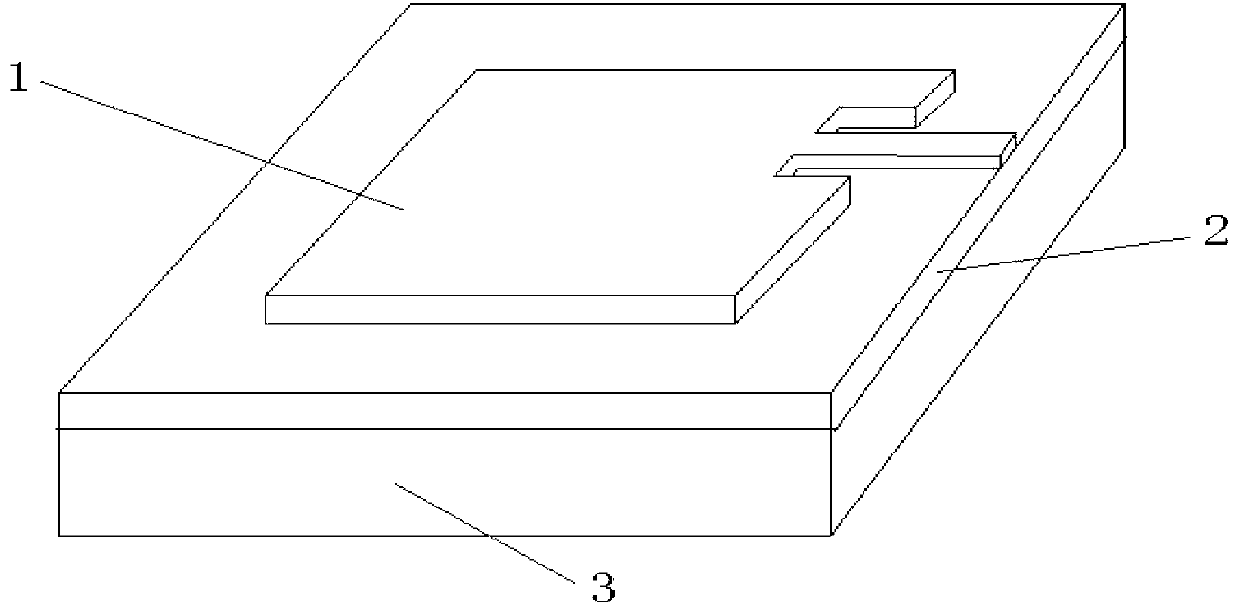
[0037] The material of the dielectric substrate 2 is polytetrafluoroethylene (R4B-265), a sheet with a size of 40mm*40mm*0.5mm, and the material of the conductor patch 1 is copper, and a metal film with a size of 16mm*20mm*0.035mm. The metal structure 3 to be tested is made of copper, a metal plate with a size of 40mm*40mm*3mm, and the corresponding theoretical resonant frequencies of the sensor designed in this way are 4.59GHz and 5.68GHz. When the sensor is working, the length and direction of the crack can be obtained by measuring the drift of the resonance frequency.

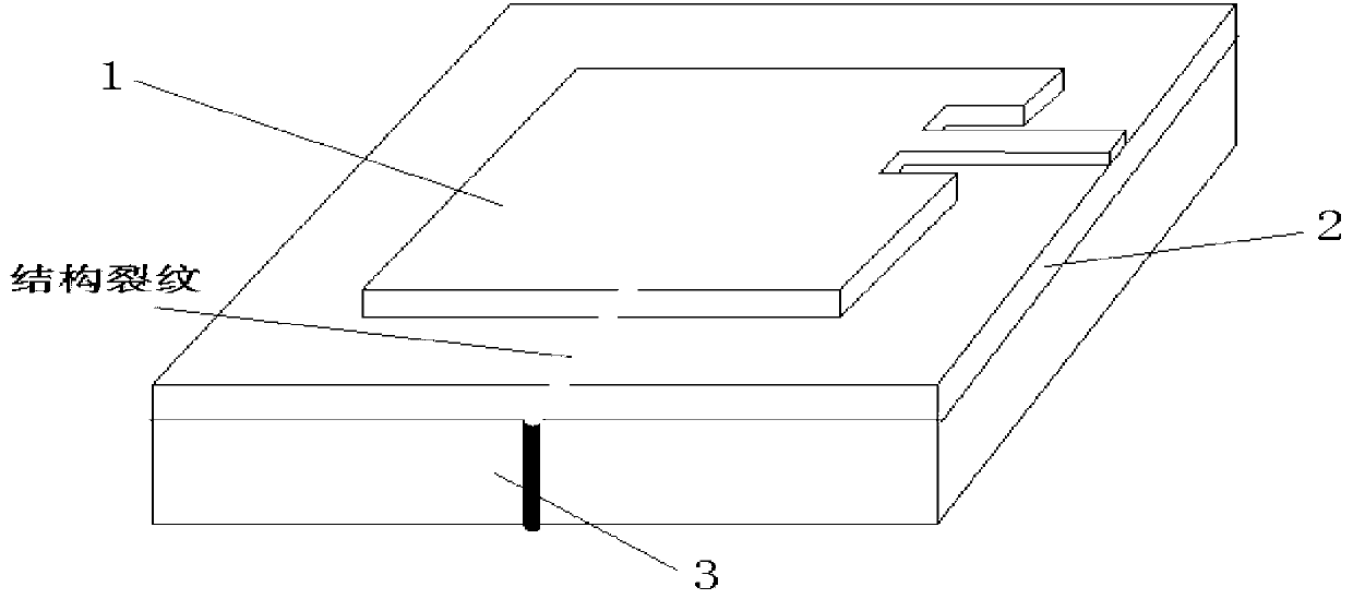
[0038] Such as figure 2 , taking the detection of the central crack length along the patch length as an example. As the crack length increases, due to the resonant frequency f parallel to the patch length direction 01 basically unchanged, the resonant frequency f parallel to the width direction 10 gradually decreases, for this crack length depends on the resonant frequency f 10 The amount of drift can b...

Embodiment 2

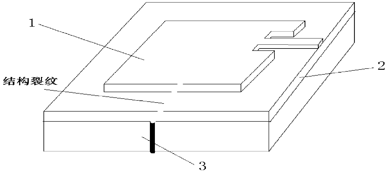
[0040]The sensor is made of laminated board Rogers4350B. The dielectric substrate 2 is a sheet with a size of 40mm*25mm*0.44mm. The material of the conductor patch 1 is copper, and the size is a metal film with a size of 15.25mm*12.75mm*0.035mm. The material of the metal structure 3 to be tested is LY12CZ aluminum alloy plate, the size is 40mm*25mm*5mm, and the corresponding resonant frequency of the sensor designed in this way is 5.1GHz and 6.1GHz. When the sensor is working, the length and direction of the crack can be obtained by measuring the drift of the resonance frequency.

[0041] Such as image 3 As shown, any central crack parallel to the length direction of the microstrip antenna, when the crack length coincides with the microstrip antenna patch extends from 0 to 15mm, the corresponding resonant frequency f 10 Decreasing from 6.1GHz to 2.5GHz, the crack length is roughly linear with the frequency drift, and the detection sensitivity is 0.24GHz / mm.

[0042] Such as...


PUM

PropertyMeasurementUnit
Resonant frequencyaaaaaaaaaa

Abstract

The invention provides a crack detection sensor based on a microstrip antenna and a detection method thereof. The invention is characterized in that the crack detection sensor comprises a dielectric substrate, one surface of the dielectric substrate is provided with a conductor patch through etching, deposition or corrosion, and the other surface of the dielectric substrate is adhered on a to-be-detected structure to form the complete sensor. According to the invention, a relationship between the length and the direction of a crack and resonant frequencies of radiation modes respectively parallel to the length direction and the width direction of the patch of the microstrip antenna can be established, and the length and the direction of the crack can be obtained based on the shifts of the resonant frequencies. The crack detection sensor based on the microstrip antenna provided by the invention has the advantages of a small size, light weight, low profile, capacity of being conformal to a carrier, simple manufacturing, low cost, etc.; moreover, the crack detection sensor employs microwave detection technology, which facilitates wireless detection and signal processing.

Description

technical field [0001] The invention relates to the technical fields of structural crack monitoring and structural health monitoring, in particular to a crack detection sensor based on a microstrip antenna and a detection method thereof, which can detect the length and direction of cracks. Background technique [0002] The construction of many large and complex engineering structures, such as large-scale aircraft, super-long-span bridges, super-long-span space structures for large-scale sports events, super high-rise buildings, large-scale water conservancy projects, offshore platform structures, and nuclear power plant buildings, etc., have a service life of several years. Ten years or even hundreds of years, the coupling effect of environmental erosion, material aging and long-term effects of load, fatigue and sudden change will inevitably lead to damage accumulation and resistance attenuation of structures and systems, which will lead to catastrophic damage in extreme case...

Claims


Application Information

Patent Timeline
Patent Type & Authority Applications(China)
IPC IPC(8): G01N22/02
Inventor 刘马宝李浩葛航宇李斌斌
Owner XI AN JIAOTONG UNIV
Why Eureka
Try Eureka