Pyrolysis and combustion coupled circular reaction method and device

A combustion cycle and reaction device technology, used in the production of combustible gas, direct heating and dry distillation, preparation of liquid hydrocarbon mixtures, etc. The effect of large production capacity of equipment, small heat loss of equipment and enhanced pyrolysis capacity

Inactive Publication Date: 2013-10-23
张荣光
View PDF7 Cites 22 Cited by
  • Summary
  • Abstract
  • Description
  • Claims
  • Application Information

AI Technical Summary

Problems solved by technology

The main disadvantages of the above process are: the process is long and there are many equipments; the heat of pyrolysis reaction is only provided by high-temperature circulating ash, because the quantity is limited, which limits the production capacity of the pyrolysis reactor, thereby reducing the overall system efficiency. production capacity, or reduce the degree of pyrolysis of solid carbonaceous substances, resulting in a decrease in the yield of oil and gas products; the pyrolysis gas generated during the pyrolysis process cannot be exported as soon as possible, and there are problems such as long contact time with high-temperature materials, so it will Causes more pyrolysis gases to undergo secondary reactions, thereby reducing oil yield
[0007] In order to provide more heat for the pyrolysis reaction and reduce the export resistance of pyrolysis gas, Chinese patent ZL201110098415.3 discloses a technical solution, that is, another heating furnace (chamber) is built outside the pyrolysis reactor, through A built-in component with good heat transfer performance is set in the solid material filling layer (one end is connected to the heating furnace) to transfer the heat of the heating furnace to the pyrolysis reactor, so that the pyrolysis reaction heat can be jointly provided by the high-temperature circulating ash and the heating furnace ; There is a gap between the wall surface of the internal member and the carbonaceous material to provide a discharge channel f

Method used


Image

  • Pyrolysis and combustion coupled circular reaction method and device
  • Pyrolysis and combustion coupled circular reaction method and device

Examples


Embodiment 1

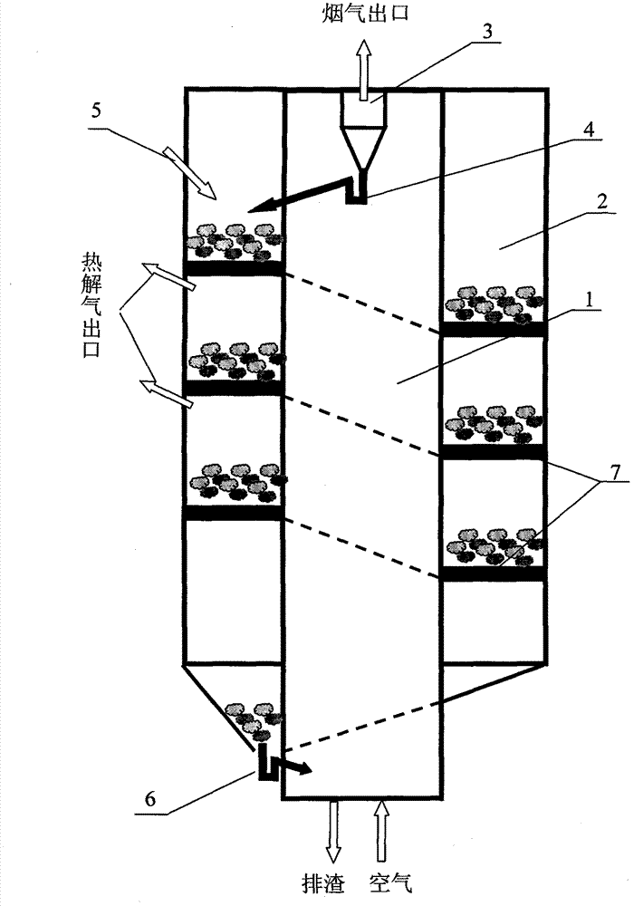
[0041] The pyrolysis coupled combustion cycle reaction device is an integrated device with a double sleeve structure in which the inner cylinder is a combustion chamber. figure 1 As shown, it includes: feeding mechanism 5, fluidized bed combustion chamber 1, pyrolysis chamber 2, gas-solid separation mechanism 3, flue gas outlet, upper feeding mechanism 4, lower feeding mechanism 6, pyrolysis gas outlet, air inlet and the slag outlet, wherein the fluidized bed combustion chamber 1 is the inner cylinder of the device, the annular space between the inner cylinder and the outer cylinder is the pyrolysis chamber 2, and the upper part of the fluidized bed combustion chamber 1 is provided with a gas-solid separation mechanism 3, and its gas phase The outlet is connected to the flue gas outlet, and its solid phase outlet is connected to the upper part of the pyrolysis chamber through the upper feeding mechanism 4. The upper part of the pyrolysis chamber is provided with a feeding mecha...

Embodiment 2

[0044] This embodiment is an improved device of embodiment 1, such as figure 1 As shown, except that a spirally descending plate structure guide member 7 is set in the pyrolysis chamber 2, the remaining parts are the same as in Embodiment 1. One side of the guide member is connected with the wall surface of the fluidized bed combustion chamber, and the other side is connected with the wall surface of the pyrolysis chamber.

[0045] In this embodiment, since the flow guide member 7 connected with the high-temperature wall of the fluidized bed combustion chamber is arranged in the pyrolysis chamber, the following beneficial effects will be produced: 1. The wall of the pyrolysis chamber constitutes the solid flow channel. Because the flow guide member has good thermal conductivity, these three walls are in a high temperature state, which strengthens the indirect heating process of the solid material in the pyrolysis chamber; The height of the solid material in the above-mentione...

Embodiment 3

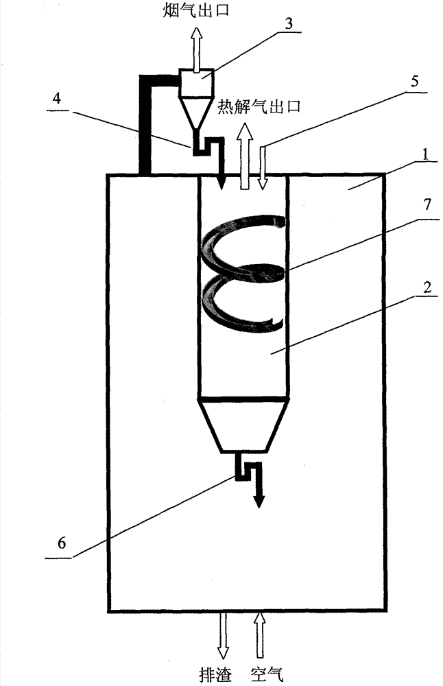
[0047] The pyrolysis coupled combustion cycle reaction device is an integrated device with a double-sleeve structure whose inner cylinder is a pyrolysis chamber, such as figure 2 As shown, it includes: feeding mechanism 5, fluidized bed combustion chamber 1, pyrolysis chamber 2, gas-solid separation mechanism 3, flue gas outlet, upper feeding mechanism 4, lower feeding mechanism 6, pyrolysis gas outlet, air inlet and the ash outlet, wherein the pyrolysis chamber 2 is the inner cylinder of the device, the annular space between the inner cylinder and the outer cylinder is the fluidized bed combustion chamber 1, and the upper part of the fluidized bed combustion chamber 1 is provided with a gas-solid separation mechanism 3, and its inlet It is connected to the fluidized bed combustion chamber, its gas phase outlet is connected to the flue gas outlet, and its solid phase outlet is connected to the upper part of the pyrolysis chamber through the upper feeding mechanism 4. The pyrol...


PUM


Abstract

The invention relates to a pyrolysis and combustion coupled circular reaction method and device. The method and the device are used for converting fine-grained carbon containing materials such as coal, biomasses and oil shale into oil, gas, heat and other products through fast pyrolysis and combustion. The device mainly comprises a fluidized-bed combustion chamber, a pyrolysis chamber and a solid circulation system. Compared with the prior art, the method has the advantages that the pyrolysis and combustion coupling process is shortened due to the integration of the structures and the functions of the pyrolysis and the combustion, and the device is compact in structure, has high degree of integration and high thermal efficiency and occupies a small floor area. The pyrolysis reaction can be carried out by both a high-temperature wall surface or heat-conducting component obtained by combusting semicoke in the fluidized-bed combustion chamber and a solid heat carrier, thus the pyrolysis capacity, the equipment production capacity and the oil, gas and heat recovery rate can be improved.

Description

Technical field: [0001] The present invention relates to the field of carbon-containing solid fuel energy chemical industry. Specifically, the present invention relates to a pyrolysis coupled combustion cycle reaction method and device, which convert fine-grained carbon-containing substances into oil, gas, Method and apparatus for heating products. The carbonaceous substances referred to here include coal, biomass, oil shale, etc., or their mixtures. Background technique: [0002] China's energy resource reserves are dominated by coal, and there is a serious shortage of oil and natural gas resources. By the end of 2009, China's proven coal reserves accounted for 13.9% of the world's total, while oil and natural gas accounted for only 1.1% and 1.3% respectively. The shortage of oil and natural gas is one of the main problems in my country's energy industry, especially the shortage of oil has become a serious problem that limits my country's future economic development and t...

Claims


Application Information

Patent Timeline
IPC IPC(8): C10B49/22C10B49/10C10B53/00C10J3/62C10J3/60C10J3/54C10C1/00C10G1/00
CPCY02P20/129
Inventor 张荣光
Owner 张荣光
Why Eureka
Try Eureka