
Crystalline silicon solar cell and manufacturing method thereof

The technology of a solar cell and a manufacturing method, which is applied in the field of solar cells, can solve the problems of increased battery series resistance, reduced electrode cross-sectional area, increased electrode resistance, etc., and achieves the effects of improving conversion efficiency, low manufacturing cost, and improving efficiency

Inactive Publication Date: 2013-11-13
上海太阳能工程技术研究中心有限公司
View PDF4 Cites 4 Cited by
  • Summary
  • Abstract
  • Description
  • Claims
  • Application Information

AI Technical Summary

Problems solved by technology

However, a decrease in the width of the fine grid naturally causes a decrease in the cross-sectional area of ​​the electrode, which leads to an increase in the electrode resistance, that is, the increase in the battery series resistance

Method used


Image

  • Crystalline silicon solar cell and manufacturing method thereof

Examples


Embodiment Construction

[0018] The present invention will be described in detail below in conjunction with the accompanying drawings and specific embodiments.

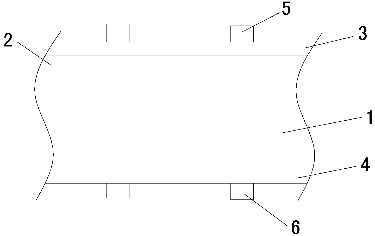
[0019] see figure 1 The crystalline silicon solar cell of the present invention comprises a crystalline silicon wafer 1 with a PN junction, and a layer of transparent conductive film 3 and 4 is respectively deposited on the front and back sides of the crystalline silicon wafer with a PN junction. Copper grid line electrodes 5 and 6 are respectively electroplated on the conductive film. figure 1 As shown in , 2 is the diffused n-region.

[0020] The thickness of the transparent conductive film in the present invention is 20nm-80nm; the width of the copper grid electrode is 30μm-60μm.

[0021] The transparent conductive film among the present invention is ITO (nano indium tin metal oxide) thin film or ZnO thin film, IWO thin film (indium tungsten oxide), TiO 2 film or other transparent conductive oxide films.

[0022] The preparation method...


PUM

PropertyMeasurementUnit
thicknessaaaaaaaaaa
widthaaaaaaaaaa

Abstract

The invention provides a crystalline silicon solar cell and a manufacturing method of the crystalline silicon solar cell. The manufacturing method includes the steps that a crystalline silicon slice with PN junctions is used as a substrate, two layers of transparent conducting thin films are deposited on the front and the back of the substrate respectively, and electroplating copper grid line electrodes are arranged on the transparent conducting thin films on the front and the back of the substrate respectively. According to the crystalline silicon solar cell and the manufacturing method of the crystalline silicon solar cell, SiNx is replaced by TCO, and silk-screen printing silver grid lines are replaced by electroplating copper. Due to the fact that the silk-screen printing silver grid lines are replaced by the electroplating copper, electrode grid lines can be more exquisite, smaller in light shielding area, and lower in cost because silver is replaced by copper. Due to the fact that the TCO has high light transparency and electrical conductivity, antireflective films and the inactivation effect of the SiNx can be replaced, a certain effect for collecting current is achieved, the number of the grid lines can be reduced, more importantly, the electroplating copper can be resisted from infiltrating into silicon, and the defects in the process of directly electroplating copper on a silicon cell are overcome. In addition, cost of TCO production equipment is far lower than cost of SiNx production equipment. The TCO and the electroplating copper are combined, therefore, manufacturing cost is low, the preparing process is simple, and efficiency of the cell can be effectively improved.

Description

technical field [0001] The invention relates to a solar cell, in particular to a crystalline silicon solar cell and a manufacturing method thereof. Background technique [0002] The traditional manufacturing process of crystalline silicon cells is to form a pn junction by diffusion on the cleaned and textured crystalline silicon wafer, then remove the PSG and edge, then coat a layer of anti-reflection film SiNx, and finally screen-print the front and back electrodes and Back electric field, sintered. The battery generates photogenerated carriers under the irradiation of light, and the current is exported by the electrodes at both ends of the pn junction connected with the outside world. The front electrode should try to avoid blocking the incident light to ensure that most of the incident light enters the pn junction, and it must also fully collect the photogenerated carriers. These are two contradictory requirements. The current technology is to use a metal grid electrode ...

Claims


Application Information

Patent Timeline
Patent Type & Authority Applications(China)
IPC IPC(8): H01L31/068H01L31/0224H01L31/18
CPCY02E10/50Y02E10/547Y02P70/50
Inventor 郭群超柳琴庞宏杰王凌云白晓宇张愿成张滢清
Owner 上海太阳能工程技术研究中心有限公司
Learn More