Liquid flow frame structure for flow cell and electric pile formed by flow cell

A technology of liquid flow battery and liquid flow frame, which is applied in the direction of fuel cell grouping, fuel cell components, fuel cells, etc., which can solve problems such as uneven voltage, large flow resistance, and increased battery voltage difference, and achieve pressure and flow uniformity, improve energy efficiency, and prolong service life

Active Publication Date: 2014-09-17
HUNAN YINFENG NEW ENERGY
View PDF4 Cites 0 Cited by
  • Summary
  • Abstract
  • Description
  • Claims
  • Application Information

AI Technical Summary

Problems solved by technology

The generation of bypass current also causes other problems: due to the large potential difference between the terminal anode and the cathode, and the direct electrolyte channel, an electrochemical reaction different from the battery system itself will occur on the two electrodes at this time
In this way, the liquid flow distribution among the individual cells is uneven, resulting in uneven voltage between the cells, increasing the voltage difference between different cells, thereby reducing the energy conversion efficiency of the battery
[0006] On the other hand, the electrode of the flow battery is a carbon felt with a porous and loose structure, and there is a large flow resistance when the electrolyte flows through the electrode.
At this time, if there is a gap between the liquid flow frame and the electrode, the electrolyte will flow through the gap between the electrode and the liquid flow frame, and there is nothing around the reaction area of ​​the ordinary liquid flow frame that can prevent the electrolyte from flowing through the side of the electrode. structure, thereby reducing the reaction efficiency of the single cell

Method used


Image

  • Liquid flow frame structure for flow cell and electric pile formed by flow cell
  • Liquid flow frame structure for flow cell and electric pile formed by flow cell

Examples


Embodiment Construction

[0022] The present invention will be described in more detail below in conjunction with the accompanying drawings.

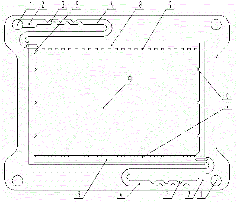
[0023] Such as figure 1 As shown, the flow battery flow frame of the present invention includes a positive electrode flow frame and a negative electrode flow frame. The main flow pipe located inside the liquid flow frame and connected to the external liquid storage tank. The inlet of the main flow pipe is the liquid inlet and outlet 1 provided on the surface of the liquid flow frame. The section 3 and the serpentine channel 4 communicate with the distribution channel 8 , and the distribution channel 8 communicates with the reaction zone 9 . A distribution grid 7 is arranged on the side of the distribution channel 8 close to the reaction zone 9 . The tops of both sides of the reaction zone 9 are provided with flow blocking blocks 5 , and the two sides of the reaction zone ( 9 ) are provided with flanges 6 .

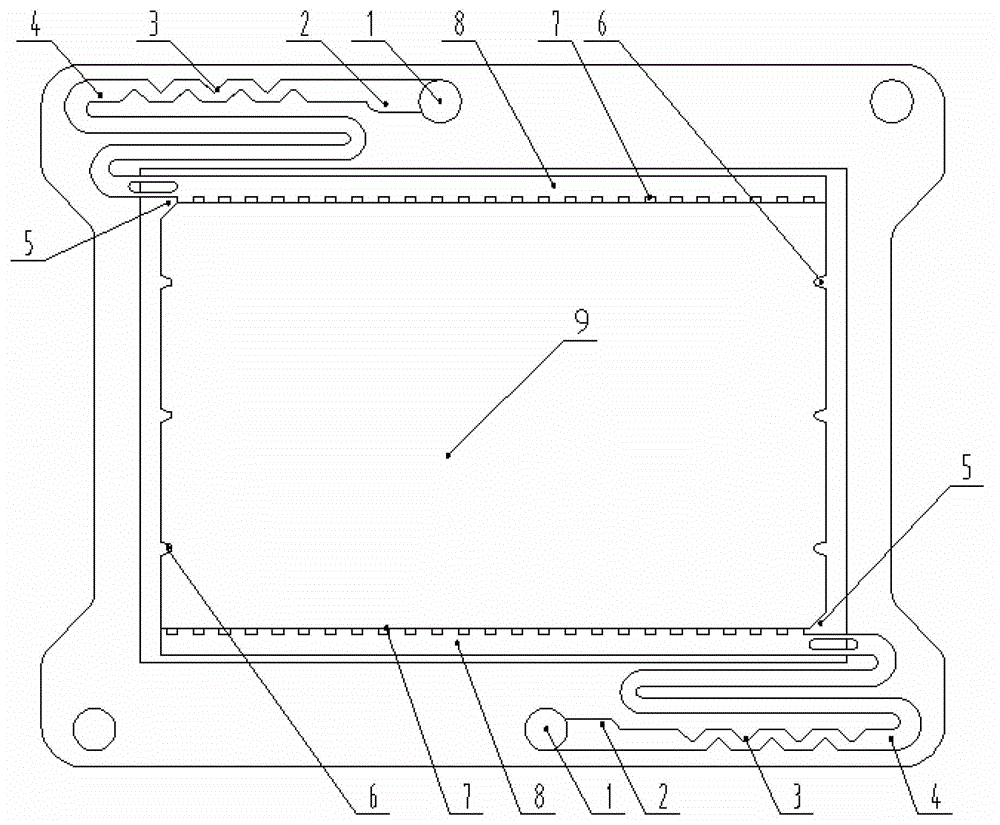
[0024] figure 2 It is another embodiment of the l...


PUM


Abstract

The invention discloses a liquid flow frame structure of a liquid flow battery and an electric stack composed of the same. The liquid flow frame structure includes a positive electrode flow frame and a negative electrode flow frame. The mainstream pipeline connected with the external liquid storage tank, the inlet of the mainstream pipeline is the liquid inlet and outlet located on the surface of the liquid flow frame, and the liquid inlet and outlet successively pass through the pressure stabilizing chamber, the tooth-shaped flow limiting section, the serpentine flow channel and the distribution The flow channel is connected, and the distribution flow channel is connected to the reaction zone. The structure of the present invention not only solves the technical problem of a large voltage difference between the cells due to uneven liquid flow, but also keeps the voltage difference between the cells within a small range, greatly improving the stability and safety of the vanadium battery It also effectively increases the impedance of the conductive path of the electrolyte, reduces the self-discharge of the bypass current, and prevents the electrolyte from flowing through the side of the reaction zone, improving the reaction efficiency of the electrolyte.

Description

technical field [0001] The present invention relates to a liquid flow battery, in particular to a flow frame structure of a liquid flow battery and an electric stack composed of the same. Background technique [0002] Flow batteries, especially all-vanadium redox flow batteries (referred to as vanadium batteries, VRB), are a new type of high-efficiency and large-capacity energy storage battery with long life and high safety. Smooth output, in the future, there will be broad application space in the vast new energy fields, such as wind power generation, photovoltaic power generation, smart grid, etc. [0003] For the current common bipolar stack vanadium battery pack, the internal mainstream pipeline is a common electrolyte channel formed by superimposing the inlet and outlet ports of the liquid flow frame, so that the electrolyte enters each battery through the mainstream pipeline and branch circuits , so that there are ion channels between different batteries. And becaus...

Claims


Application Information

Patent Timeline
Patent Type & Authority Patents(China)
IPC IPC(8): H01M8/02H01M8/24H01M8/026H01M8/0263H01M8/2483
CPCY02E60/50
Inventor 胡永清吴雄伟尹兴荣萧荣滔吕善光
Owner HUNAN YINFENG NEW ENERGY
Why Eureka
Try Eureka