Electrochemical oxidation device

An oxidation device and electrochemical technology, applied in the direction of sterilization/microdynamic water/sewage treatment, etc., can solve the problems of increased treatment cost, increased system processing capacity, environmental hazards, etc., to improve biodegradability and strengthen electrochemical Degradation effect, effect of reducing chroma

Active Publication Date: 2013-11-27
KUNMING UNIV OF SCI & TECH
View PDF5 Cites 8 Cited by
  • Summary
  • Abstract
  • Description
  • Claims
  • Application Information

AI Technical Summary

Problems solved by technology

[0003] The existing coking wastewater treatment methods can be mainly divided into physical and chemical methods and biochemical methods. The biochemical method is the most effective and widely used method for coking wastewater treatment so far because of its low treatment cost. At present, optimized methods are mostly used in China. The coking wastewater is treated by the activated sludge method. After the treatment, the effluent contains two indicators of phenol and cyanide, which can meet the requirements of the discharge standard, but the concentration of COD and ammonia nitrogen is still high, which is harmful to the environment. The advanced oxidation technology is precisely because of An emerging treatment technology developed to deal with the needs of such high-concentration refractory pollutants. This type of technology uses electricity, light, radiation and catalysts to generate free radicals with strong oxidizing ability to degrade macromolecules in water. Organic matter is oxidized and degraded into low-toxic or non-toxic small molecular substances, or even directly degraded into harmless components such as carbon dioxide, water and inorganic ions, but generally consumes a lot of energy and has high processing costs
[0004] A / O, A 2 The implementation of / O and other combined processes requires supporting equipment. In the coking wastewater treatment plant, the core unit is the reactor, and the commonly used reactors are ordered batch activated sludge reactor (SBR), solid bed reactor and good reactor. Oxygen fluidized bed reactor, etc., but the above reactor is directly used as A 2 In the case of anaerobic and anoxic reactors in the supporting treatment device of the / O process, the concentration of ammonia nitrogen in the influent water must be lower than 250 mg / L to make the concentration of ammonia nitrogen in the effluent water lower than 15 mg / L to achieve standard discharge. Therefore, the wastewater to be treated enters A large amount of dilution must be carried out before the reactor, so that the system can run stably, which leads to an increase in the processing capacity of the system and an increase in processing costs

Method used


Image

  • Electrochemical oxidation device
  • Electrochemical oxidation device
  • Electrochemical oxidation device

Examples


Embodiment 1

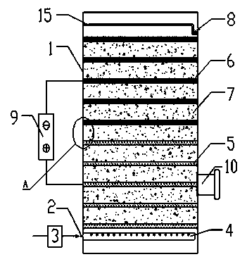
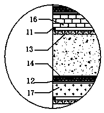
[0038] The electrochemical oxidation device in this embodiment includes a housing 1, a water inlet 2, a liquid distributor 4, an anode bed 5, a cathode bed 6, a micro-electrolysis packing layer 7, a water outlet 8, a power supply 9, a packing outlet 10, a packing The pressure plate 13, the overflow weir 15, the water inlet 2 is set at the lower part of the shell 1, the liquid distributor 4 is set at the water inlet, the anode bed 5 with more than 4 layers is set above the liquid distributor 4, and the anode bed 5 is set 4 The cathode bed 6 above the layer, the anode bed 5 or the cathode bed 6 are arranged on the packing plate 13, the micro-electrolysis packing layer 7 is filled between the anode bed or the cathode bed and the packing plate 13, and the overflow weir 15 is arranged on the shell 1 On the inner wall, the overflow weir 15 is set on the shell 1, and the water outlet 8 is set on the shell 1, which is higher than the bottom of the overflow weir 15 in the vertical direc...

Embodiment 2

[0056]The electrochemical oxidation device in this embodiment includes a housing 1, a water inlet 2, a liquid distributor 4, an anode bed 5, a cathode bed 6, a micro-electrolysis packing layer 7, a water outlet 8, a power supply 9, a packing outlet 10, a packing The pressure plate 13, the overflow weir 15, the water inlet 2 is set at the lower part of the shell 1, the liquid distributor 4 is set at the water inlet, the anode bed 5 with more than 4 layers is set above the liquid distributor 4, and the anode bed 5 is set 4 The cathode bed 6 above the layer, the anode bed 5 or the cathode bed 6 are arranged on the packing plate 13, the micro-electrolysis packing layer 7 is filled between the anode bed or the cathode bed and the packing plate 13, and the overflow weir 15 is arranged on the shell 1 On the inner wall, the overflow weir 15 is set on the shell 1, and the water outlet 8 is set on the shell 1, which is higher than the bottom of the overflow weir 15 in the vertical direct...

Embodiment 3

[0074] The electrochemical oxidation device in this embodiment includes a housing 1, a water inlet 2, a liquid distributor 4, an anode bed 5, a cathode bed 6, a micro-electrolysis packing layer 7, a water outlet 8, a power supply 9, a packing outlet 10, a packing The pressure plate 13, the overflow weir 15, the water inlet 2 is set at the lower part of the shell 1, the liquid distributor 4 is set at the water inlet, the anode bed 5 with more than 4 layers is set above the liquid distributor 4, and the anode bed 5 is set 4 The cathode bed 6 above the layer, the anode bed 5 or the cathode bed 6 are arranged on the packing plate 13, the micro-electrolysis packing layer 7 is filled between the anode bed or the cathode bed and the packing plate 13, and the overflow weir 15 is arranged on the shell 1 On the inner wall, the overflow weir 15 is set on the shell 1, and the water outlet 8 is set on the shell 1, which is higher than the bottom of the overflow weir 15 in the vertical direc...


PUM

PropertyMeasurementUnit
diameteraaaaaaaaaa
diameteraaaaaaaaaa
lengthaaaaaaaaaa

Abstract

The invention discloses an electrochemical oxidation device which comprises a housing, a water inlet, a liquid distributor, an anode bed, a cathode bed, a micro-electrolysis packing layer, a water outlet, a power supply, a stuffing discharging port, a filler pressure plate and an overflow dam. The device uses coking wastewater containing phenyl hydroxide contaminant as a processing object, allows the degradation-resistant organic materials to change into carbon dioxide, water, inorganic ions and other innocuous substances through oxidative degradation by utilizing an electrochemical oxidation system formed by the cathode bed and the anode bed, wherein the anode material of the oxidation system can improve the hydroxyl free radical generating rate to accelerate organic materials oxidative degradation efficiency. Compared with a traditional electrochemical method, the energy consumption required for processing the waste water is reduced, spiral strip-shaped carbon steel chips are adopted as micro-electrolysis stuffing, and the processing effect is ensured while the cost is saved. The device is easy to manage, simple to operate and stable in running.

Description

technical field [0001] The invention relates to an electrochemical oxidation device, which belongs to the field of coking wastewater pollution control. Background technique [0002] Coking wastewater mainly comes from coking, gas purification, and refining of chemical products. It produces a large amount of high-concentration organic wastewater mainly containing phenolic compounds. The water quality is complex and varies with raw coal and coking processes. Aromatic organic compounds, heterocyclic and polycyclic compounds are a kind of industrial wastewater that is difficult to treat. [0003] The existing coking wastewater treatment methods can be mainly divided into physical and chemical methods and biochemical methods. The biochemical method is the most effective and widely used method for coking wastewater treatment so far because of its low treatment cost. At present, optimized methods are mostly used in China. The coking wastewater is treated by the activated sludge me...

Claims


Application Information

Patent Timeline
Patent Type & Authority Applications(China)
IPC IPC(8): C02F1/467
Inventor 瞿广飞裘伟霞吴淼淼宁平张健
Owner KUNMING UNIV OF SCI & TECH
Why Eureka
Try Eureka