
Preparation method of SrTiO3 nano composite film photoanode

A nano-composite and photoanode technology, applied in the field of photoanode, can solve the problems of low photoelectric conversion efficiency, fast photo-generated carrier recombination speed, etc., and achieve good photoelectric effect, excellent photo-generated cathodic protection effect, coating and complete effect.

Inactive Publication Date: 2013-12-25
XIAMEN UNIV
View PDF2 Cites 13 Cited by
  • Summary
  • Abstract
  • Description
  • Claims
  • Application Information

AI Technical Summary

Problems solved by technology

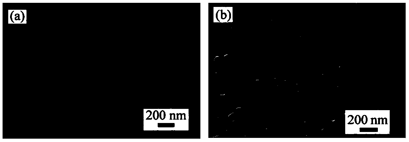
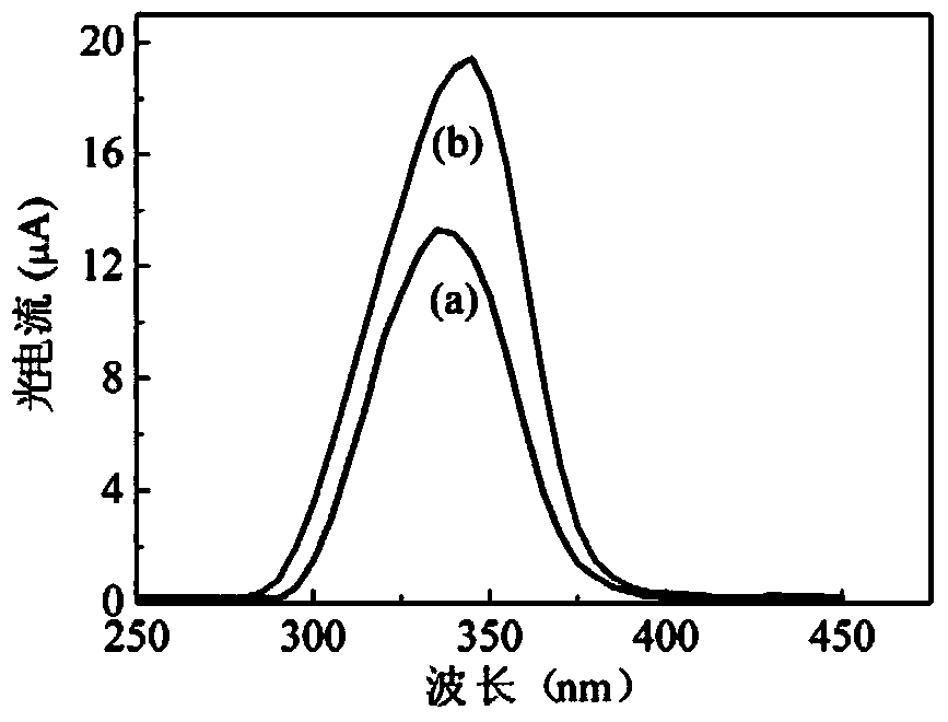
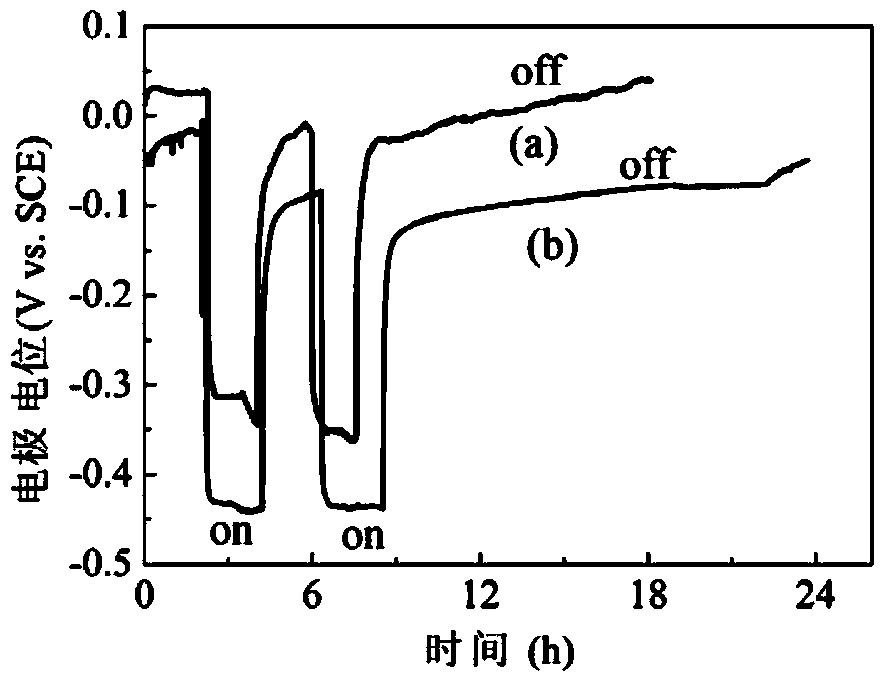
[0005] The purpose of the present invention is to overcome single TiO 2 To solve the problems of fast recombination speed of photogenerated carriers and low photoelectric conversion efficiency of nanomaterials, we provide a SrTiO with high-efficiency photogenerated cathodic protection effect 3 Preparation method of nanocomposite film photoanode

Method used


Image

  • Preparation method of SrTiO3 nano composite film photoanode
  • Preparation method of SrTiO3 nano composite film photoanode
  • Preparation method of SrTiO3 nano composite film photoanode

Examples


Embodiment 1

[0025] According to the above technical scheme (specific steps), prepare SrTiO 3 Nanocomposite film photoanode, and test the cathodic protection effect of the photoanode on 403 stainless steel.

[0026] Take a 0.1mm thick rectangular pure titanium foil as a sample (purity>99.7%), its length is 1.5cm, and its width is 1.0cm. Sequentially ultrasonic cleaning in acetone, absolute ethanol and deionized water for 30 min.

[0027] Anodizing solution composition: NH 4 F content is 0.5wt%, glycerol: water (volume ratio) = 3:2. With titanium foil as anode and platinum sheet as cathode, anodize in the above solution for 1h. After the reaction was completed, it was washed with a large amount of deionized water, dried, and put into a muffle furnace for heat treatment at 450° C. for 120 minutes.

[0028] Cover the prepared surface with TiO 2 The titanium foil of the nanotube array film was placed in a polytetrafluoroethylene reactor, and 0.01M Sr(OH) was added 2 Solution 40mL, reacte...

Embodiment 2

[0035] Take a 0.1mm thick rectangular pure titanium foil as a sample (purity>99.7%), which is 1.5cm long and 1.0cm wide. Sequentially ultrasonic cleaning in acetone, absolute ethanol and deionized water for 30 min.

[0036] Anodizing solution composition: NH 4 F content is 0.5wt%, glycerol: water (volume ratio) = 3:2. With titanium foil as anode and platinum sheet as cathode, anodize in the above solution for 1h. After the reaction is finished, wash with a large amount of deionized water, dry and put it into a muffle furnace for heat treatment at 450°C for 120min.

[0037] Cover the prepared surface with TiO 2 The titanium foil of the nanotube array film was placed in a polytetrafluoroethylene reactor, and 0.01M Sr(OH) was added 2 Solution 40mL, react at 180°C for 1h, take out the sample and soak in 0.01M HCl solution for 1min, then rinse with a large amount of deionized water, dry and calcinate in a muffle furnace at 450°C for 120min. That is, the prepared SrTiO 3 and T...


PUM

PropertyMeasurementUnit
thicknessaaaaaaaaaa
lengthaaaaaaaaaa
widthaaaaaaaaaa

Abstract

The invention relates to a photoanode, particularly a preparation method of a SrTiO3 nano composite film photoanode. The invention provides a preparation method of a SrTiO3 nano composite film photoanode with efficient photogenerated cathode protection effect. The preparation method comprises the following steps: 1) preparation of titanium base: applying ultrasonic on a titanium foil used as a base to obtain a titanium base; 2) preparation of TiO2 nanotube array film: carrying out anodization reaction by using the titanium base as an anode and a platinum sheet as a cathode, cleaning, drying and calcining to obtain a TiO2 nanotube array film on the titanium base; and 3) preparation of SrTiO3 nano composite film photoanode: putting the titanium base coated with the TiO2 nanotube array film prepared in the step 2) into a teflon reaction kettle, adding a Sr(OH)2 solution, reacting, immersing in a HCl solution, cleaning, drying, and calcining to obtain the SrTiO3 nano composite film photoanode. The SrTiO3 nano composite film photoanode is a SrTiO3 / TiO2 composite material in a P-N heterostructure.

Description

technical field [0001] The invention relates to a photoanode, in particular to SrTiO with good photogenerated cathodic protection performance 3 Preparation method of nanocomposite film photoanode. Background technique [0002] The development and prosperity of the world economy benefit from non-renewable fossil resources. However, fossil resources are rapidly approaching depletion, and their use produces serious environmental pollution. Facing the double pressure of economic development and environmental protection, the development of renewable energy is a difficult problem that human beings must solve. Solar energy is an inexhaustible and inexhaustible renewable energy source, and more importantly, it does not produce environmental pollution during use. Photoelectric conversion is an important aspect of solar energy utilization. It is mainly based on semiconductor materials and uses light to generate electron-hole pairs, thereby generating photocurrent and photovoltage ph...

Claims


Application Information

Patent Timeline
Patent Type & Authority Applications(China)
IPC IPC(8): H01L31/18B82Y40/00
CPCY02P70/50
Inventor 杜荣归朱燕峰徐璐胡娟林昌健
Owner XIAMEN UNIV
Learn More