
Separation recovery method of enameling technique exhaust

An enamelling process, separation and recovery technology, applied in separation methods, semi-permeable membrane separation, chemical instruments and methods, etc., can solve problems such as reducing energy recovery efficiency, environmental pollution, and recovery efficiency needs to be improved

Inactive Publication Date: 2014-01-15
韩富生
View PDF1 Cites 1 Cited by
  • Summary
  • Abstract
  • Description
  • Claims
  • Application Information

AI Technical Summary

Problems solved by technology

This not only consumes valuable film-forming substances but also increases the emission of greenhouse gases. At the same time, it also wastes energy, reduces energy utilization efficiency, and greatly increases the cost of equipment. The price of each enameled oven is as high as one million US dollars. The above increases the production cost of manufacturing enameled wire, thus limiting the popularization and use of this type of equipment
[0007] To sum up, the catalytic combustion technology is currently used in enamelled ovens; although this technology partially solves the environmental pollution problem caused by enamelled tail gas, it also partially recovers the combustion heat of organic solvent vapor and saves energy, but it still There is a problem of greenhouse gas carbon dioxide emissions; at the same time, the high temperature generated by the combustion of organic solvent vapor is difficult for the equipment itself to completely digest, and it has to discharge high-temperature gas into the atmosphere, which reduces the efficiency of energy recovery; at the same time, organic solvents are used as energy substitutes. Not worth the candle
[0008] My invention patent application "Recovery Method and Device for Enamelling Process Tail Gas" (Application No.: 2008100540752) involves a condensation recovery method and device for enamelling process tail gas, and the recovery efficiency needs to be improved

Method used


Image

  • Separation recovery method of enameling technique exhaust
  • Separation recovery method of enameling technique exhaust
  • Separation recovery method of enameling technique exhaust

Examples


Embodiment 1

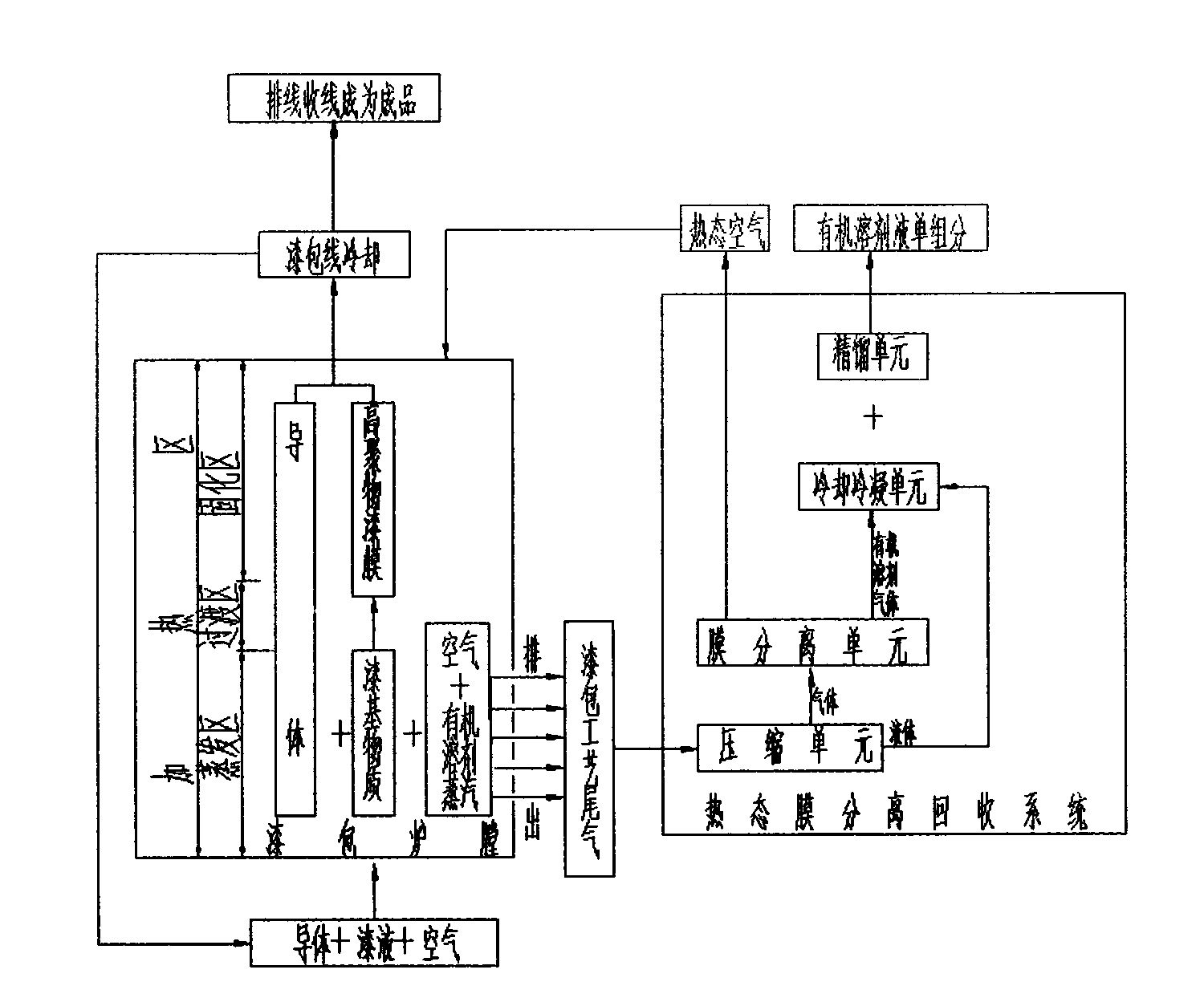
[0025] Example 1: figure 2 The flow chart of the present invention's hot-state membrane separation recovery enamelling process tail gas; as figure 2 As shown, when the conductor is coated with varnish liquid and air enters the enamelled furnace for heating, when the organic solvent in the lacquer liquid reaches the volatilization temperature, it begins to volatilize gradually, becomes solvent vapor and mixes with the air in the furnace to become enamelled process tail gas, At this time, the fan sucks the high-temperature enamelled tail gas out of the inner furnace of the enamelled furnace from the evaporation area of ​​the enamelled furnace in time, discharges it continuously and injects it into the hot membrane separation and recovery system.

[0026] The thermal membrane separation recovery system consists of compression, membrane separation, cooling condensation and rectification units in sequence.

[0027] When the hot enamelling process tail gas enters the compression ...

Embodiment 2

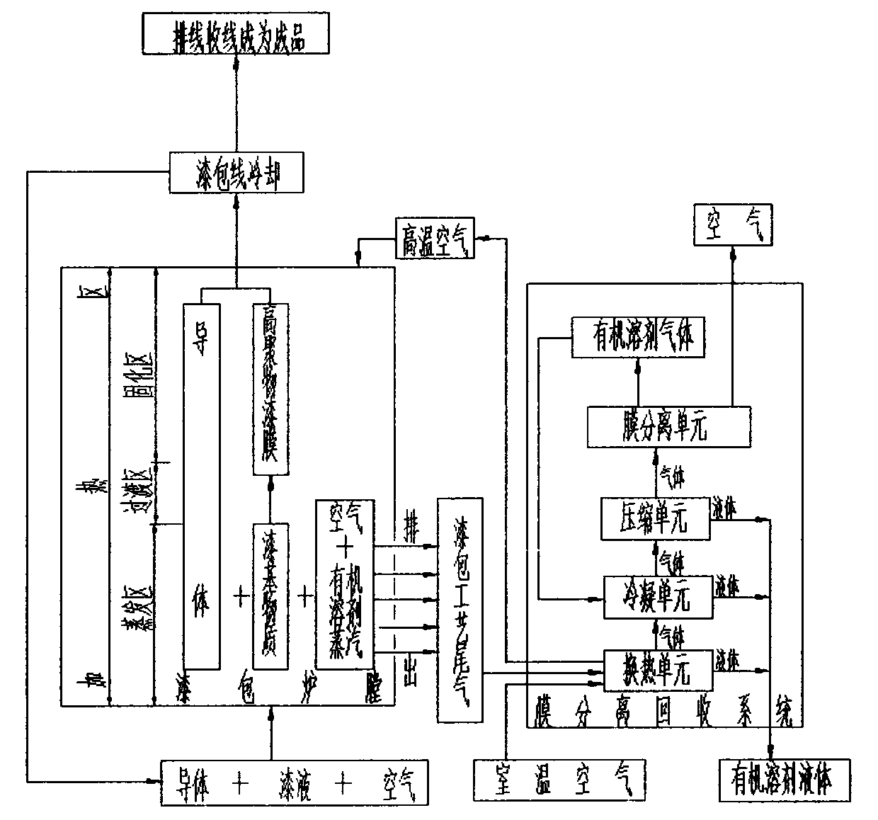
[0032] image 3 The flow chart of the present invention's cold state direct method membrane separation recovery enamelling process tail gas; image 3 As shown, when the conductor is coated with varnish liquid and air enters the enamelled furnace for heating, when the organic solvent in the lacquer liquid reaches the volatilization temperature, it begins to volatilize gradually, becomes solvent vapor and mixes with the air in the furnace to become enamelled process tail gas, At this time, the fan sucks the high-temperature enamelled tail gas out of the inner furnace of the enamelled furnace from the evaporation area of ​​the enamelled furnace in time, discharges it continuously and injects it into the hot membrane separation and recovery system.

[0033] The cold-state membrane separation direct method recovery system consists of a heat exchange unit, a compression unit, a condensation unit, and a membrane module separation unit in sequence.

[0034] When the enamelling proces...

Embodiment 3

[0039] Figure 4 The flow chart of the present invention's cold-state deoxygenation and nitrogen removal method membrane separation recovery enamelling process tail gas; Figure 4 As shown, when the conductor is coated with varnish liquid and air enters the enamelled furnace for heating, when the organic solvent in the lacquer liquid reaches the volatilization temperature, it begins to volatilize gradually, becomes solvent vapor and mixes with the air in the furnace to become enamelled process tail gas, At this time, the fan sucks the high-temperature enamelled tail gas out of the inner furnace of the enamelled furnace from the evaporation area of ​​the enamelled furnace in time, discharges it continuously and injects it into the hot membrane separation and recovery system.

[0040] The cold-state membrane separation direct method recovery system consists of a heat exchange unit, a compression unit, a condensation unit, and a membrane module separation unit in sequence.

[00...


PUM


Abstract

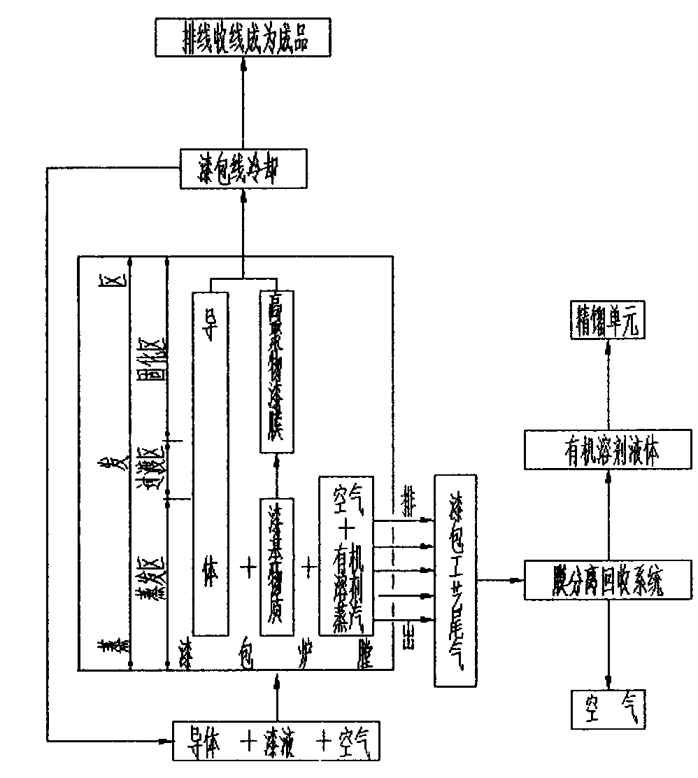
The invention discloses a separation recovery method of enameling technique exhaust, which comprises the following steps: A. after a conductor is enameled, the conductor enters the inside of an enameling hearth together with air; B. in the evaporation region, an organic solvent is volatilized into enameling technique exhaust; C. the enamel-base substance is continuously heated to generate a high polymer enamel film, and enters a room temperature space to be cooled; D. after repeated circulations, the wire is taken up by a winding; D. the recovery method also comprises the step of discharging the enameling technique exhaust out of the hearth in time between the step B and the step C; and F. the enameling exhaust is continuously injected into a membrane separation recovery system on line. The method has the following advantages: the solvent which is catalytically burnt up and stilled used in the existing enameled wire industry is subjected to organic solvent vapor-air separation through a membrane component, and recovered to obtain an organic solvent liquid; and the organic solvent liquid is rectified to obtain the organic solvent. Compared with other modes for treating enameling technique exhaust, the membrane separation recovery of enameling technique exhaust has the advantages of no toxicity, no emission, energy saving, consumption reduction and effect enhancement.

Description

technical field [0001] The invention relates to a method for separating and recovering industrial waste gas; in particular, it relates to a method for separating and recovering process tail gas in enameled wire production. Background technique [0002] Enameled oven is a special equipment for producing enameled wire. The enameled wire is composed of a conductor and an insulating paint film, and is usually used to wind into a coil for mutual conversion between electromagnetics, and is widely used in various electronic and electrical products. [0003] The production process of the existing enameled wire is: conductor unwinding→annealing→painting→heating and drying→wire winding (finished product). The painting process is to apply insulating varnish on the surface of the conductor. In order to obtain an insulating varnish film with uniform geometric dimensions, the insulating varnish is usually composed of varnish-based substances and organic solvents. Organic solvents accoun...

Claims


Application Information

Patent Timeline
Patent Type & Authority Applications(China)
IPC IPC(8): B01D61/00B01D5/00
Inventor 韩富生
Owner 韩富生
Learn More