Device and method for producing clean gasoline by combining catalytic cracking and hydrofining

A hydrofining and catalytic cracking technology, which is applied in the fields of hydrotreating process, petroleum industry, and hydrocarbon oil treatment, can solve the problem of coupling of catalytic cracking and hydrofining systems, increase of energy consumption and equipment investment, and unrelated Waiting for the question

Inactive Publication Date: 2014-02-12
CHINA UNIV OF PETROLEUM (EAST CHINA) +1
View PDF30 Cites 8 Cited by
  • Summary
  • Abstract
  • Description
  • Claims
  • Application Information

AI Technical Summary

Problems solved by technology

However, none of the above patents involves the olefin-reducing treatment of olefin-rich light gasoline, which makes heavy-distillate gasoline need to reach a certain olefin saturation rate in the hydrogenation process to make the final product gasoline meet the requirements of the latest gasoline standards
Another problem is that the above patents all cut the catalytic cracking stable gasoline, so the catalytic gasoline is very likely to have been cut twice, thereby increasing energy consumption and equipment investment
Patent CN101294108A proposes to separate light and heavy fractions of catalytic gasoline in the catalytic cracking product separation system, and then carry out hydrofining of heavy fractions, but it does not involve the improvement of absorption-stabilization system flow and the treatment of light gasoline rich in olefins. Upgrading does not involve the systematic coupling of the two processes of catalytic cracking and hydrofinishing

Method used


Image

  • Device and method for producing clean gasoline by combining catalytic cracking and hydrofining
  • Device and method for producing clean gasoline by combining catalytic cracking and hydrofining
  • Device and method for producing clean gasoline by combining catalytic cracking and hydrofining

Examples


Embodiment 1

[0065] Embodiment 1: Two-stage riser reactor

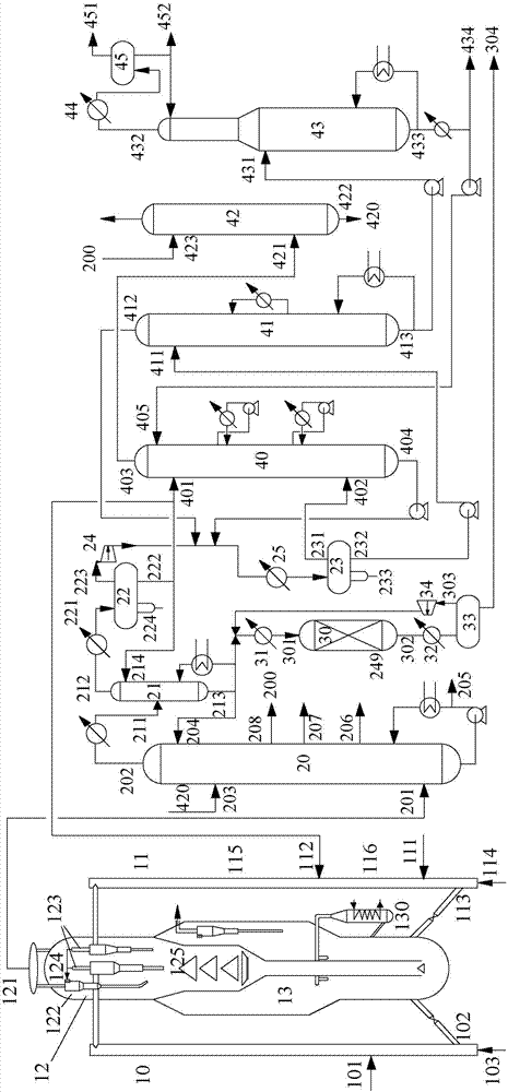
[0066] Such as figure 1 As shown, the device for the combined production of clean gasoline by catalytic cracking and hydrofinishing provided in this example includes a reaction-regeneration system, a fractionation system, a hydrofinishing unit and an absorption-stabilization system,

[0067] Among them, the reaction-regeneration system includes a riser reactor, an oil separator and a catalyst regenerator,

[0068] The riser reactor is a two-stage riser reactor, comprising a first riser reactor 10 and a second riser reactor 11, the upper end of the first riser reactor 10 communicates with the oil separator 12, and the second riser reactor The upper end of the tube reactor 11 communicates with the oil separator 12, and the first riser reactor 10 is provided with a pre-lift gas inlet 103, a catalyst feed port 102 and a feedstock oil feed port 101 from bottom to top, and the second riser reactor The device 11 is provided with a pre-...

Embodiment 2

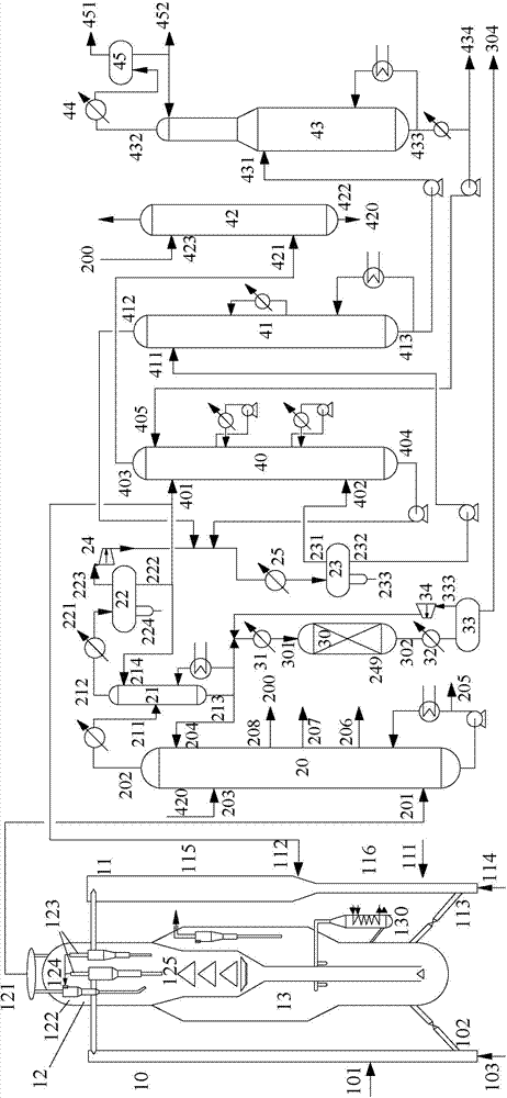
[0080] The device of the present invention see figure 2 , its structure is basically the same as that of Example 1, except that the second riser reactor adopts a combination reactor of a fast bed and a transport bed. Such as figure 2 As shown, the second riser reactor is composed of the pre-lift section, the transport bed reaction zone and the fast bed reaction zone from bottom to top. The specific design requirements are as follows: the total height of the reactor is 30~60m; 5%~20% of the height, the height of the transport bed reaction zone accounts for 30~60% of the total height of the reactor, and its diameter is 1.0~2.0 times the diameter of the pre-lifting section; the height of the fast bed reaction zone accounts for 20% of the height of the riser reactor ~50%, its diameter is 1.5~5.0 times of the diameter of the conveying bed reaction zone; among them, the pre-lifting section is provided with pre-lifting gas inlet 114 and catalyst feed port 113 from bottom to top, a...

Embodiment 3

[0082] Embodiment 3: single-stage riser reactor

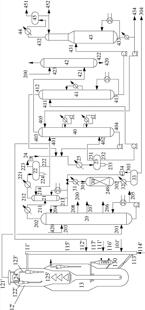
[0083] Such as image 3 As shown, the device for the joint production of clean gasoline by catalytic cracking and hydrofining provided in this example is similar to Example 1, except that the riser reactor of the reaction regeneration system in this example is a single-stage riser reactor.

[0084] Knot image 3 , the difference between the two devices is described as follows:

[0085] The upper end of the riser reactor 11' communicates with the oil separator 12', and the riser reactor 11' is provided with a pre-lift gas inlet 114', a catalyst feed port 113', a raw oil feed port 101', Circulating oil feed port 111' and naphtha light fraction feed port 112', the solid phase outlet of the oil separator 12' communicates with the catalyst regenerator 13, and the catalyst regenerator 13 communicates with the catalyst of the riser reactor 11' through pipelines. The feeding port 113' is connected;

[0086] The oil separator 12' in...


PUM


Abstract

The invention discloses a device and method for producing clean gasoline by combining catalytic cracking and hydrofining. The device comprises a reaction-regeneration system, a fractionating system, an absorption stable system and a hydrofining unit. The method comprises the following steps: adding a gasoline fractionating tower to the top of a catalytic cracking fractionating tower to divide crude gasoline into a light fraction and a heavy fraction, wherein the heavy fraction gasoline enters the hydrofining unit for selective hydrogenation desulfurization, and one part of the light fraction gasoline enters the absorption stable system to obtain stable light gasoline, and the other part of the light fraction gasoline directly returns to a reaction area at the upper part of a catalytic cracking second riser reactor to be modified under a mild condition; and blending the stable light gasoline and the modified heavy gasoline to obtain the product of clean gasoline. By adopting the method, the catalytic cracking gasoline is efficiently modified, and the catalyst-oil ratio of a catalytic cracking device can be increased to promote the conversion of heavy petroleum hydrocarbon; and meanwhile, the load and energy consumption of the absorption stable system are reduced, the synergistic effect between the two devices of catalytic cracking and hydrofining is enhanced, and the processing cost is lowered.

Description

technical field [0001] The invention relates to a catalytic conversion process and a hydrotreating process of petroleum hydrocarbons, in particular to a combined upgrading method of catalytic conversion and hydrofining of catalytic cracked gasoline, which belongs to the technical field of petrochemical industry, and specifically relates to a method for utilizing catalytic cracking and hydrogenation A device and method for combined production of clean gasoline by hydrogen refining. Background technique [0002] Although the octane number of olefins is high, but the chemical properties are active, NO x Mixed and irradiated by the sun's ultraviolet rays, it will form toxic photochemical smog, which will cause serious pollution to the atmosphere; on the other hand, because olefins, especially dienes with conjugated structures, are extremely unstable, it is easy to form colloids in the engine oil intake system, nozzles and cylinders permanent deposits, affecting engine efficienc...

Claims


Application Information

Patent Timeline
Patent Type & Authority Applications(China)
IPC IPC(8): C10G67/00
Inventor 贾少磊张金弘山红红杨朝合刘文菁陈小博李春义
Owner CHINA UNIV OF PETROLEUM (EAST CHINA)
Why Eureka
Try Eureka