Technology and device for recovering volatile tail gas in sulfur collection pit of sulfur device of oil refinery

A sulfur device and tail gas recovery technology, which is applied in the direction of combustion method, lighting and heating equipment, combustion type, etc., can solve the problems of incinerator energy consumption, environmental pollution, and the inability to recover volatile tail gas sulfur, etc., so as to reduce the concentration and reduce the The effect of energy consumption

Active Publication Date: 2014-02-19
JIANGSU WISDOM ENG TECH
View PDF4 Cites 9 Cited by
  • Summary
  • Abstract
  • Description
  • Claims
  • Application Information

AI Technical Summary

Problems solved by technology

[0002] In the prior art, for the treatment of volatile tail gas (the main component is hydrogen sulfide) in the sulfur collection pit of the refinery sulfur plant, it is generally used to discharge directly without treatment, or to use the sulfur component in the combustion tail gas of the incinerator to generate Discharge of sulfur dioxide; no matter which method is used, it will cause environmental pollution and energy consumption of incinerators
In the existing technology, it is impossible to recover volatile tail gas to generate product sulfur, reduce the amount of sulfur components leading to the incinerator, so as to achieve the purpose of reducing sulfur dioxide emissions and reducing the energy consumption of the incinerator

Method used


Image

  • Technology and device for recovering volatile tail gas in sulfur collection pit of sulfur device of oil refinery

Examples


Embodiment 1

[0016] A process for recovering volatile tail gas in a sulfur collection pit of a sulfur plant in an oil refinery, which is carried out according to the following steps:

[0017] (1) The volatile tail gas and elemental sulfur from the sulfur pit are condensed by the water jacket, the elemental sulfur returns to the sulfur pit, the volatile gas enters from the upper part of the supergravity settling reactor, the gas is sucked into the reactor, and passes through the high-speed centrifugal liquid and the stator rectification mechanism Segmentation, the gas is sheared and broken into micro-bubbles and evenly dispersed in the desulfurization solution, so that rapid mass transfer, absorption and oxidation reactions occur between the gas-liquid two phases. The desulfurization solution absorbs the hydrogen sulfide in the gas phase into the liquid phase to generate divalent sulfide ions; the catalyst oxidizes the divalent sulfide ions into elemental sulfur. The main components of the ...

Embodiment 2

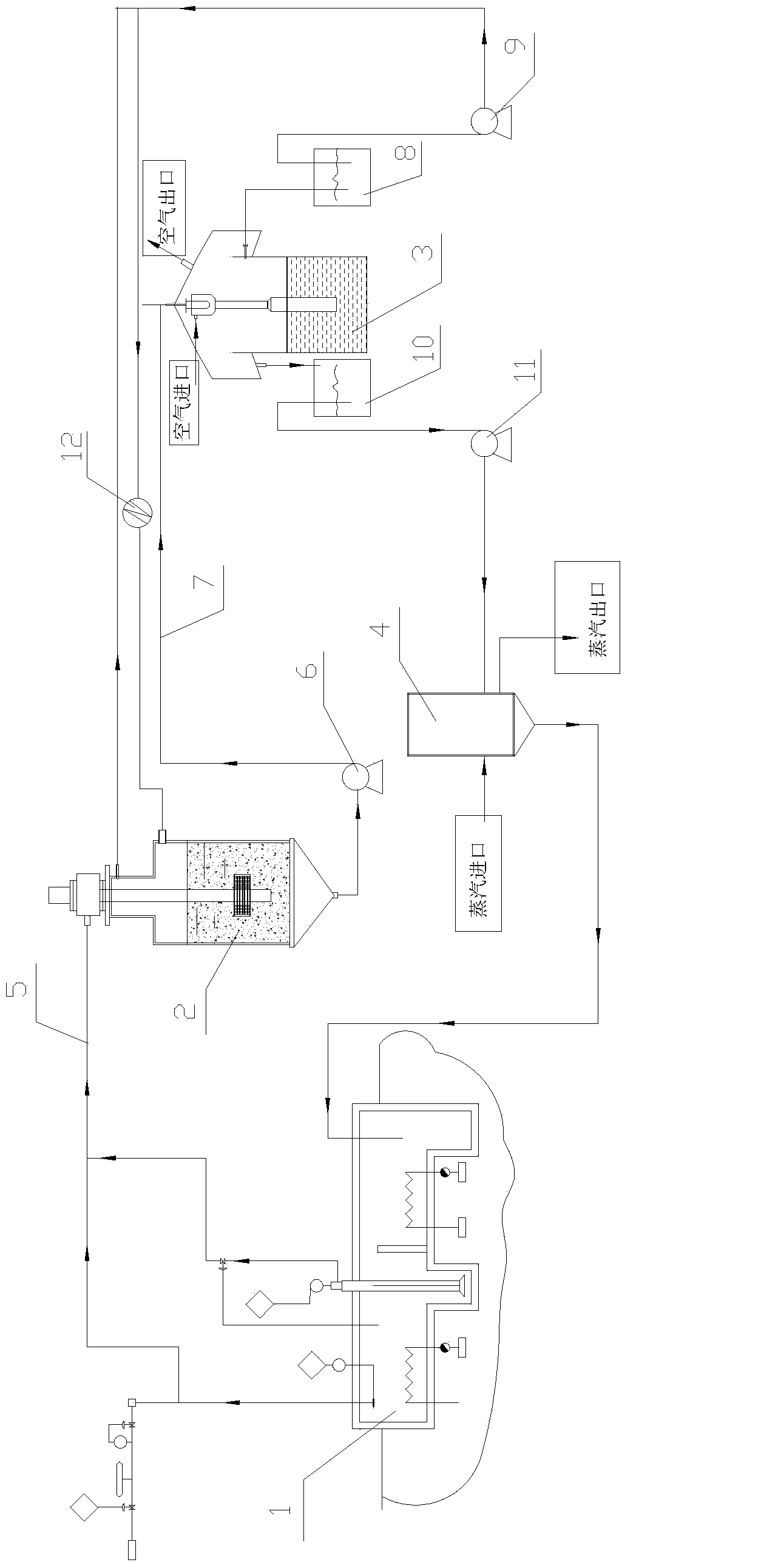
[0022] This embodiment is a recovery device for volatile tail gas in the sulfur collection pit of a sulfur plant in an oil refinery. The equipment is connected as follows: figure 1 As shown, it includes a high-gravity reactor 2, a spray regenerator 3 and a sulfur melting tank 4; the air inlet on the upper part of the high-gravity reactor is connected to the volatile tail gas of the sulfur collection pit 1 and the Elemental sulfur outlet, the liquid outlet at the bottom of the supergravity reactor 2 is connected to the rich liquid inlet at the upper part of the jet regenerator 3 through the rich liquid outlet pipe 7 provided with the rich liquid pump 6, and the upper part of the supergravity reactor 2) The outlet of the purified gas is connected to the incinerator through a pipeline; the lean liquid outlet of the injection regenerator 3 is connected to the desulfurization lean liquid tank 8 through a pipeline, and the desulfurization lean liquid tank 8 is connected to the superc...


PUM


Abstract

The invention relates to a technology and device for recovering tail gas in a sulfur collection pit, in particular to a technology and device for recovering the volatile tail gas in the sulfur collection pit of a sulfur device of an oil refinery. The technology comprises the steps as follows: firstly, a water jacket is used for condensing volatile gas and elemental sulfur in the sulfur collection pit, and condensed sulfur substance returns to the sulfur collection pit; the volatile gas in a supergravity settling reactor is absorbed by a desulfurization solution under the action of a catalyst, and is oxidized into elemental sulfur; and then the desulfurization solution containing elemental sulfur and part of hydrogen sulfide is oxidized and regenerated in a jet regenerator, elemental sulfur is subjected to flotation, returns to a sulfur melting kettle and generates a sulfur product, meanwhile, purified gas is fed into the supergravity settling reactor, discharged out from the upper part of the settling reactor and fed into a combustion furnace finally, and residual sulfur and sulfur components are removed. Therefore, the volatile gas is recovered, the sulfur product is generated, furthermore, the quantity of sulfur fed into the combustion furnace is reduced, the emission reduction of sulfur dioxide is realized, and the energy consumption of the combustion furnace is reduced.

Description

technical field [0001] The invention relates to a process and device for recovering tail gas from a sulfur collection pit, in particular to a process and device for recovering volatile tail gas in a sulfur collection pit of a sulfur plant in an oil refinery. Background technique [0002] In the prior art, for the treatment of volatile tail gas (the main component is hydrogen sulfide) in the sulfur collection pit of the refinery sulfur plant, it is generally used to discharge directly without treatment, or to use the sulfur component in the combustion tail gas of the incinerator to generate Discharge of sulfur dioxide; no matter which method is used, it will cause environmental pollution and energy consumption of the incinerator. In the prior art, it is impossible to realize the recovery of volatile tail gas to generate product sulfur and reduce the amount of sulfur components leading to the incinerator, so as to achieve the purpose of reducing sulfur dioxide emission and red...

Claims


Application Information

Patent Timeline
Patent Type & Authority Applications(China)
IPC IPC(8): B01D53/86B01D53/52B01D53/96F23G7/06
Inventor 孙立宇潘永涟刘兴朱瑞贺李翠屏牛世军
Owner JIANGSU WISDOM ENG TECH
Why Eureka
Try Eureka