
A yaw brake pad made of various materials

A brake pad and yaw technology, which is applied in the field of wind turbine braking system, can solve the problems of limited brake pad function, disappearance, and reduced braking efficiency, and achieve the goal of increasing friction coefficient and wear resistance, combining noise and reducing noise Effect

Active Publication Date: 2017-02-08
贵州新安航空机械有限责任公司
View PDF6 Cites 1 Cited by
  • Summary
  • Abstract
  • Description
  • Claims
  • Application Information

AI Technical Summary

Problems solved by technology

[0003] In the process of wind power generation, it is necessary to use the yaw brake disc to adjust the direction of the power generation blade. The yaw of the blade is realized by contacting the brake pad in the yaw brake disc with the shaft of the wind turbine. The conventional brake pad is composed of a single material. The function of the brake pads is relatively limited, and the best braking effect cannot be exerted. Some metal materials will cause high noise due to their high hardness, and may cause serious wear on the contact parts of the brake pads; while some Fiber material, its heat resistance and wear resistance are not high, need to be replaced frequently; there is also a brake pad made of a mixture of several metals and non-metals, because the temperature of each part of the brake pad is different, in the In the middle part of the brake pad, the temperature is too high due to the inability to dissipate heat. Due to the defects of some materials that are not resistant to high temperature, the braking efficiency will be lost rapidly. The braking efficiency of this part is obviously reduced or disappeared, and the brake pad will cause a lot of noise

Method used


Image

  • A yaw brake pad made of various materials
  • A yaw brake pad made of various materials

Examples


Embodiment 1

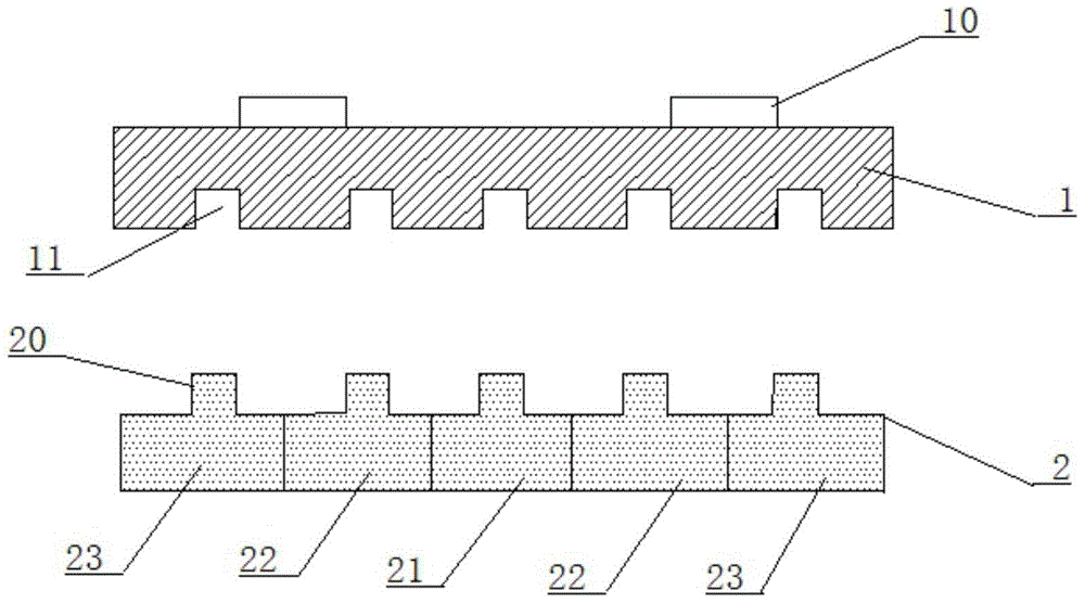
[0018] like figure 1 and figure 2 As mentioned above, a yaw brake pad made of various materials is composed of a steel back 1 and a friction layer 2, wherein the steel back 1 has a bump 10, and the place where the steel back 1 contacts the friction layer 2 has a groove 11, in order to To prevent the friction layer from falling off due to high pressure and strong vibration during high-intensity work, the insert groove 11 is designed as a square structure in cross section. At the same time, in order to ensure smooth operation of high-intensity work, the steel back is molded with high-strength steel.

[0019] The friction layer is composed of a heat-resistant layer 21, a wear-resistant layer 22 and a noise-absorbing protective layer 23 arranged sequentially from the inside to the outside, wherein there is only one piece of the heat-resistant layer 21, and the wear-resistant layer 22 and the noise-absorbing protective layer 23 are symmetrically distributed on the anti-corrosion l...

Embodiment 2

[0021] like figure 1 and figure 2 As mentioned above, a yaw brake pad made of various materials is composed of a steel back 1 and a friction layer 2, wherein the steel back 1 has a bump 10, and the place where the steel back 1 contacts the friction layer 2 has a groove 11, in order to To prevent the friction layer from falling off due to high pressure and strong vibration during high-intensity work, the insert groove 11 is designed as a square structure in cross section. At the same time, in order to ensure smooth operation of high-intensity work, the steel back is molded with high-strength steel.

[0022] The friction layer is composed of a heat-resistant layer 21, a wear-resistant layer 22 and a noise-absorbing protective layer 23 arranged sequentially from the inside to the outside, wherein there is only one piece of the heat-resistant layer 21, and the wear-resistant layer 22 and the noise-absorbing protective layer 23 are symmetrically distributed on the anti-corrosion l...

Embodiment 3

[0024] like figure 1 and figure 2 As mentioned above, a yaw brake pad made of various materials is composed of a steel back 1 and a friction layer 2, wherein the steel back 1 has a bump 10, and the place where the steel back 1 contacts the friction layer 2 has a groove 11, in order to To prevent the friction layer from falling off due to high pressure and strong vibration during high-intensity work, the insert groove 11 is designed as a square structure in cross section. At the same time, in order to ensure smooth operation of high-intensity work, the steel back is molded with high-strength steel.

[0025] The friction layer is composed of a heat-resistant layer 21, a wear-resistant layer 22 and a noise-absorbing protective layer 23 arranged sequentially from the inside to the outside, wherein there is only one piece of the heat-resistant layer 21, and the wear-resistant layer 22 and the noise-absorbing protective layer 23 are symmetrically distributed on the anti-corrosion l...


PUM


Abstract

The invention discloses a yaw brake pad made of various materials. The yaw brake pad is composed of a steel back (1) and a friction layer (2), and the friction layer (2) is formed by sequentially arranging a heat-resistant layer (21), a friction-resistant layer (22) and a denoising protection layer (23) from inside to outside. The heat-resistant layer (21) contains boron-modified phenolic resin and vanadium trioxide, so that hardness, heat resistance and instant high temperature resistance of the friction layer are improved; the friction-resistant layer (22) contains steel wool fibers, quartz sand and potassium hexatitanate, so that friction coefficient and friction resistance of the friction layer are improved; the denoising protection layer (23) contains materials, large in nonmetal content, like flake graphite, molybdenum disulfide and antimony sulfide, so that the yaw brake pad is low in noise during working, and noise inside the yaw brake pad can be shielded. Friction performance, friction resistance and denoising effect of the yaw brake pad are obviously improved, service life of the yaw brake pad is longer than that of a common yaw brake pad, and the only defect of the yaw brake pad is that contact parts are worn slightly.

Description

technical field [0001] The invention relates to a wind power generator braking system, in particular to a yaw brake pad made of various materials. Background technique [0002] Wind energy, as a renewable energy source, has attracted more and more attention from all countries. With the advancement of technology and the advocacy of sustainable development, wind power generation has flourished all over the world. The pollution-free and renewable nature of wind power has made wind power generation popular in various countries. There is a lot of room for development under policies such as sustainable development and energy-saving strategies. According to the latest research report released by Deutsche Bank, the global wind power development is entering a stage of rapid expansion, and the wind power industry will maintain an annual growth rate of 20%. By 2015 By 2020, the total output value of the industry will increase to five times the current level. [0003] In the process of...

Claims


Application Information

Patent Timeline
Patent Type & Authority Patents(China)
IPC IPC(8): F16D69/00F16D69/02F03D7/00B22F1/00C22C38/12C22C49/00
CPCY02E10/72
Inventor 范艳芳
Owner 贵州新安航空机械有限责任公司
Learn More