Main drying unit of slurry or powder continuous drying system
A drying system and drying technology, applied in non-progressive dryers, dryers, drying of solid materials, etc., can solve the problems of low production efficiency, inability to achieve continuous work, etc., achieve high production efficiency, facilitate heat exchange, and facilitate Quick discharge effect
- Summary
- Abstract
- Description
- Claims
- Application Information
AI Technical Summary
Problems solved by technology
Method used
Image

Examples
Embodiment 1
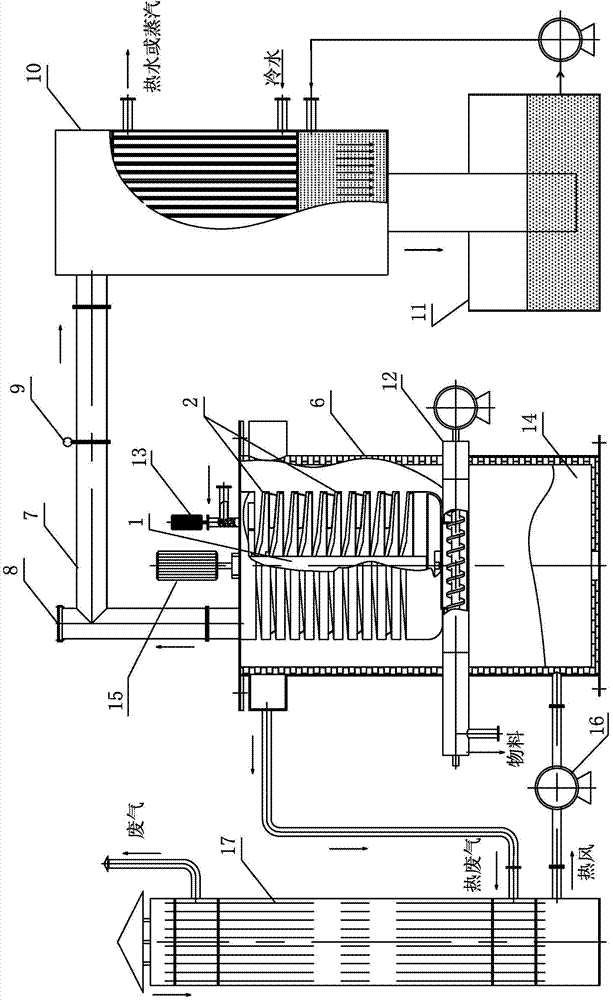
[0042] See Figure 1-7 The continuous drying system for slurry or powder provided in this embodiment includes: a drying host, and a collection system for collecting volatiles connected to the exhaust port of the drying host.
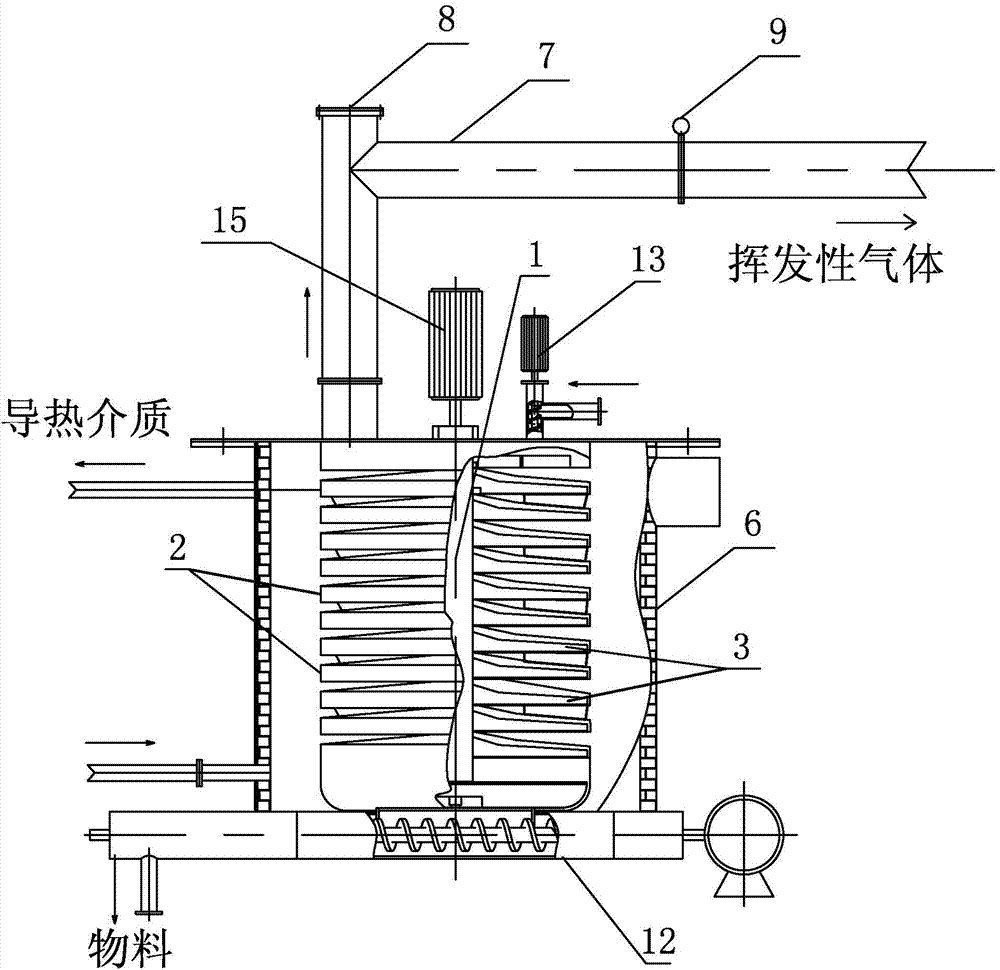
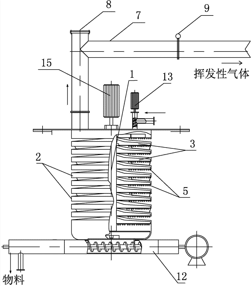
[0043] The main drying machine includes: a main shaft 1, an annular cavity 2 arranged up and down in multiple layers; The scraper 3; there is an inter-chamber gap between two adjacent annular chambers 2, so that the bottom plate of the annular chamber 2 can directly exchange heat with the heat-conducting medium or the heating wire, thereby ensuring the drying effect.
[0044] Two adjacent annular cavities 2 are sealed and connected by a blanking channel 4; the bottom of the bottom plate of each annular cavity 2 is provided with a heating wire 5, or each annular cavity is arranged in a thermal fluid container 6, or the The drying host is set above a combustion furnace 14; the top annular cavity is provided with a material inlet and an exhaust port for di...
Embodiment 2
[0056] The working method of the continuous drying system of the slurry or powder described in the above-mentioned embodiment 1, comprising:
[0057] A. Connect the heating wire 5 to the power supply for heating, or continuously circulate the heat-conducting liquid into the heat-conducting liquid container 6, or use the combustion furnace 14 located at the bottom of the drying host to heat each annular cavity 2; The temperature of the annular cavity 2 is suitable to reach 50-700° C. (the specific temperature needs to be selected according to different materials).
[0058] B. Input the slurry through the pump or the powder through the screw conveyor 13 from the material inlet on the annular cavity on the top floor, and at the same time turn on the main motor 15 to drive the main shaft 1 to rotate;
[0059] C. Under the action of the rotation of the scrapers 3 on each layer, the slurry or powder is heat-exchanged layer by layer, dried and falls, and finally discharged from the d...
Embodiment 3
[0066] Such as Figures 8 to 9 , the present embodiment provides a continuous drying system for liquid materials (or slurry), including a drying host, and a collection system for collecting volatiles connected to the exhaust port of the drying host.
[0067] The drying host includes: multi-layer cavities 20 arranged up and down; there is a gap between two adjacent cavities 20, which are sealed and connected through a blanking channel; the bottom of each cavity 20 is provided with a heating wire 5, Or each cavity 20 is set in the heat transfer fluid container, or the bottom of the drying host is equipped with a combustion furnace; the cavity on the top layer is provided with a material inlet and an exhaust port, and the bottom of the cavity on the bottom layer is provided with a discharge port.
[0068] In the two adjacent cavities 20, the 1 to 4 blanking openings on the bottom plate of the upper cavity are connected to the openings on the top plate of the lower cavity through ...
PUM
 Abstract
Description
Claims
Application Information
 - R&D
- Intellectual Property
- Life Sciences
- Materials
- Tech Scout
- Unparalleled Data Quality
- Higher Quality Content
- 60% Fewer Hallucinations
Browse by: Latest US Patents, China's latest patents, Technical Efficacy Thesaurus, Application Domain, Technology Topic, Popular Technical Reports.
© 2025 PatSnap. All rights reserved.Legal|Privacy policy|Modern Slavery Act Transparency Statement|Sitemap|About US| Contact US: help@patsnap.com