Film-like circuit connection material and circuit connection structure
A circuit connection material and electrical connection technology, applied in the direction of structural connection, conductive connection, and electrical component connection of printed circuits, can solve the problems of reduced adhesion and peeling of film-like circuit connection materials, to ensure visibility, reduce Effect of connecting resistors
- Summary
- Abstract
- Description
- Claims
- Application Information
AI Technical Summary
Problems solved by technology
Method used
Image
Examples
Embodiment 1)
[0127] 400 parts by mass of polycaprolactone diol with a weight average molecular weight of 800, 131 parts by mass of 2-hydroxypropyl acrylate, 0.5 parts by mass of dibutyltin dilaurate as a catalyst, and 1.0 parts by mass of hydroquinone monomethyl ether as a polymerization inhibitor The parts were mixed by heating to 50°C with stirring. Next, 222 parts by mass of isophorone diisocyanate was dripped, and it heated up to 80 degreeC, stirring further, and performed polyurethane reaction. After confirming that the reaction rate of the isocyanate group was 99% or more, the reaction temperature was lowered to obtain urethane acrylate.
[0128] Using terephthalic acid as dicarboxylic acid, propylene glycol as diol, and 4,4'-diphenylmethane diisocyanate as isocyanate, prepare terephthalic acid / propylene glycol / 4,4'-diphenylmethane diisocyanate Polyester polyurethane resin A in which the molar ratio of isocyanate is 1.0 / 1.3 / 0.25.
[0129] Next, the polyester polyurethane resin A wa...
Embodiment 2~16)
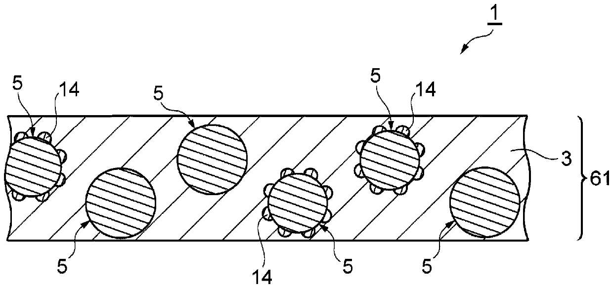
[0133] Such as Figure 5 The film-form circuit-connecting material was produced in the same manner as in Example 1, except that the average particle diameter of the conductive particles, the number of conductive particles, the type of dye, the amount of dye, and the thickness of the film-form circuit-connecting material were changed.
Embodiment 17、18)
[0135] 25 parts by mass of the above-mentioned urethane acrylate, 20 parts by mass of isocyanurate type acrylate (product name: M-325, manufactured by Toagosei Co., Ltd.), 2-methacryloxyethyl 1 part by mass of base acid phosphate (product name: P-2M), 4 parts by mass of benzoyl peroxide (product name: Nyper-BMT-K40) as a free radical generator, and 4 parts by mass as a film-forming polymer 55 parts by mass of a 20% by mass methyl ethyl ketone solution of the polyester polyurethane resin A was mixed, and 0.5 parts by mass of a black dye (product name: NUBIAN BLACK, manufactured by ORIENT Industry Co., Ltd.) was further dispersed and stirred to obtain an adhesive Components of the binder resin solution.
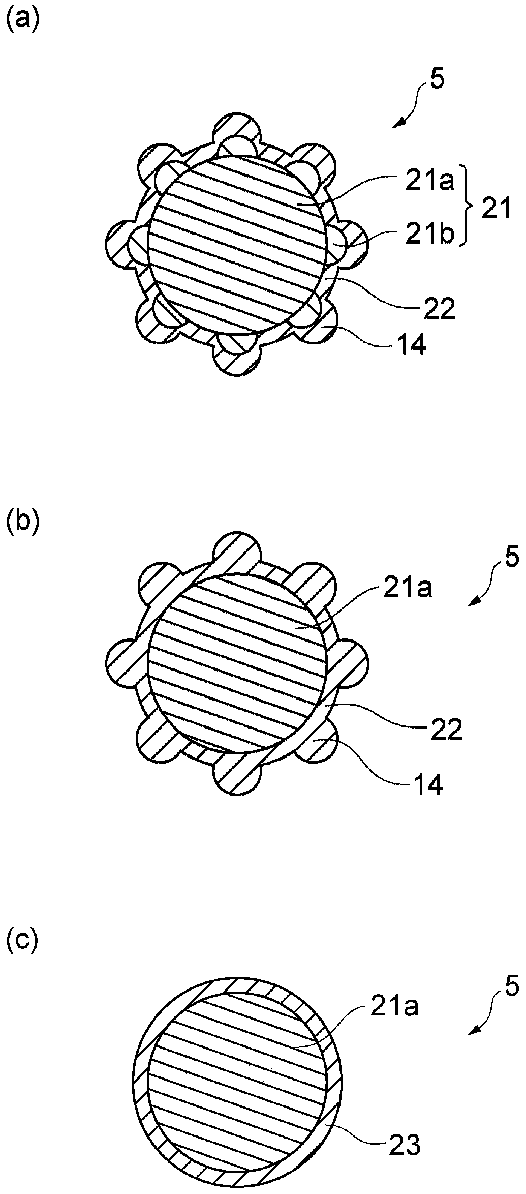
[0136] Furthermore, conductive particles (average particle diameter: 3 μm) having polystyrene particles as nuclei and coating nuclei, an outermost layer containing Ni, and protrusions formed on the surface of the outermost layer were prepared. With respect to the solution of t...
PUM
| Property | Measurement | Unit |
|---|---|---|
| particle size | aaaaa | aaaaa |
| particle size | aaaaa | aaaaa |
| particle size | aaaaa | aaaaa |
Abstract
Description
Claims
Application Information
 - R&D
- Intellectual Property
- Life Sciences
- Materials
- Tech Scout
- Unparalleled Data Quality
- Higher Quality Content
- 60% Fewer Hallucinations
Browse by: Latest US Patents, China's latest patents, Technical Efficacy Thesaurus, Application Domain, Technology Topic, Popular Technical Reports.
© 2025 PatSnap. All rights reserved.Legal|Privacy policy|Modern Slavery Act Transparency Statement|Sitemap|About US| Contact US: help@patsnap.com


