Ferrite conductive coating and preparation method thereof

A conductive coating and ferrite layer technology, which is applied in coating, metal material coating process, fusion spraying, etc., can solve the problem that the ferrite conductive coating cannot be prepared and cannot meet the requirements of the whole life of the grounding device and other problems, to achieve the effect of simple maintenance, good conductivity, and optimized process parameters

Active Publication Date: 2014-02-26
STATE GRID CORP OF CHINA +1
View PDF7 Cites 13 Cited by
  • Summary
  • Abstract
  • Description
  • Claims
  • Application Information

AI Technical Summary

Problems solved by technology

In view of the fact that the current sintering, casting and other processes are difficult to realize the preparation of large-scale ferrite products, the surface of conventional carbon steel grounding materials is coated with ferrite coating, and the grounding is improved under the premise of ensuring good electrical conductivity with the help of coating protection technology. The corrosion resistance of the device body has good application prospects in the field of grounding anti-corrosion technology
US Patent 3850701 filed by Yitai et al pointed out that the maximum thickness of the ferrite coating deposited by chemical method is only 0.02mm, which cannot meet the requirements of the whole life of the grounding device, and has not prepared a practical ferrite conductive coating
In recent years, the rapid development of plasma spraying technology has provided a good foundation for the preparation of high-performance ferrite coatings, but the compactness and conductivity of the coatings prepared by plasma spraying still need to be solved.

Method used


Image

  • Ferrite conductive coating and preparation method thereof

Examples


example 1

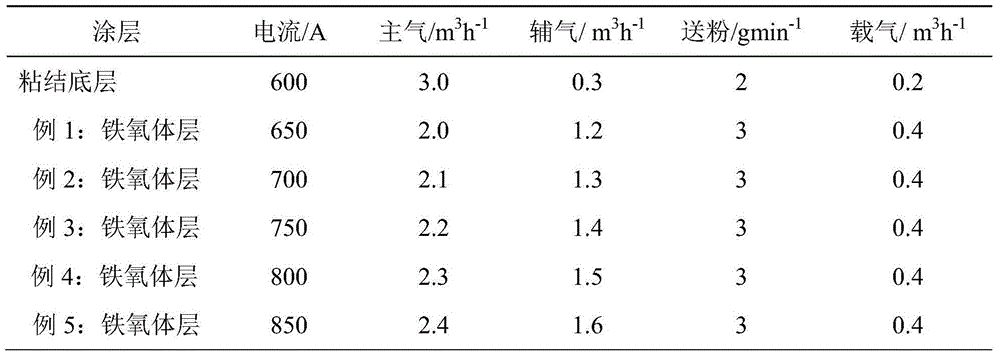
[0033] Atmospheric plasma spraying is adopted, and the bonding primer and ferrite layer shown in Table 1 are respectively used for the bonding primer and the example 1: the spraying process parameters of the ferrite layer. The ferrite spraying powder material is sprayed successively on the cleaned and sandblasted Q235 steel substrate, the bonding bottom layer is 0.15mm, and the ferrite coating is 0.20mm.

[0034] The average porosity of the ferrite conductive coating is calculated to be 2.7% with Ia32 image analysis software.

[0035] The bonding strength of the coating and the substrate was measured on a universal testing machine by the bonding tensile method, and the bonding strength of the coating was measured to be 30.0Mpa by stretching at a tensile speed of 1mm per minute.

[0036] The electrical resistance of the coating was tested by the two-terminal method and the resistivity was calculated. In order to reduce the contact resistance between the coating and the ohmmete...

Embodiment 2

[0038] Atmospheric plasma spraying is adopted, and the bonding primer and ferrite layer shown in Table 1 and Example 2: The spraying process parameters of the ferrite layer are used respectively, and the bonding primer and the ferrite layer with a particle size of 20 to 100 μm are used. The ferrite spraying powder material is sprayed successively on the cleaned and sandblasted Q235 steel substrate, the bonding base layer is 0.15mm, and the ferrite coating is 0.19mm.

[0039] The average porosity of the ferrite coating is calculated to be 2.3% with Ia32 image analysis software.

[0040] The bonding strength of the coating and the substrate was measured on a universal testing machine by the bonding tensile method, and the bonding strength of the coating was measured to be 30.2Mpa by stretching at a tensile speed of 1mm per minute.

[0041] The electrical resistance of the coating was tested by the two-terminal method and the resistivity was calculated. In order to reduce the co...

example 3

[0043]Atmospheric plasma spraying is adopted, and the bonding primer and ferrite layer shown in Table 1 and Example 3: The spraying process parameters of the ferrite layer are used respectively, and the bonding primer and the ferrite layer with a particle size of 20 to 100 μm are used. Oxygen spraying powder materials are sprayed onto the cleaned and sandblasted Q235 steel substrate successively, the bonding base layer is 0.15mm, and the ferrite coating is 0.21mm.

[0044] The average porosity of the ferrite coating was calculated to be 2.0% with Ia32 image analysis software.

[0045] The bonding strength of the coating and the substrate was measured on a universal testing machine by the bonding tensile method, and the bonding strength of the coating was measured to be 33.0Mpa by stretching at a tensile speed of 1mm per minute.

[0046] The electrical resistance of the coating was tested by the two-terminal method and the resistivity was calculated. In order to reduce the con...


PUM

PropertyMeasurementUnit
thicknessaaaaaaaaaa
particle sizeaaaaaaaaaa
thicknessaaaaaaaaaa

Abstract

The invention provides a ferrite conductive coating for resisting corrosion on electrical engineering earthing devices and a preparation method thereof. The ferrite conductive coating is a composite coating and mainly comprises a bonding base layer and a ferrite layer. The bonding base layer is coated on a base material. The ferrite layer is coated on the bonding base layer. The bonding base layer comprises Al, Zn, Co and Cu metal materials or an alloy material. The ferrite layer comprises a ferrite material having a molecular formula of MFe2O4. The composite coating has good corrosion resistance, electrical conductivity and thermal spraying adaptability. The preparation method has simple processes, a low cost and strong repeatability. The ferrite conductive coating can be used for surfaces of metal bases having different shapes or sizes, has obvious superiority in large-scale preparation of the corrosion-resistant conductive ceramic coating in practical application and is suitable for industrial popularization.

Description

【Technical field】 [0001] The invention relates to the technical field of thermal spraying coatings, in particular to a ferrite conductive coating for anticorrosion of electrical engineering grounding devices and a preparation method thereof. 【Background technique】 [0002] The grounding device is an important part of the grounding system of electrical engineering. Its quality directly affects the grounding effect, and is directly related to the safety and stability of the operation of major equipment in the power grid and the personal safety of power operators. It is understood that a large number of substations are re-laid every year due to the serious soil corrosion of grounding device materials in my country. Excavation, maintenance and replacement will cause damage and loss to the roads, grasslands and other facilities of power plants and substations, and the investment in re-laying will increase several times. , causing great economic losses. [0003] At present, most o...

Claims


Application Information

Patent Timeline
Patent Type & Authority Applications(China)
IPC IPC(8): C23C4/10C23C4/06C23C4/134
Inventor 祝志祥陈新韩钰聂京凯马光
Owner STATE GRID CORP OF CHINA
Why Eureka
Try Eureka