Multi-stage high-efficiency low-nitrogen combustion method and combustion system for circulating fluidized bed boiler

A circulating fluidized bed, low-nitrogen combustion technology, which is applied in the direction of fluidized bed combustion equipment, combustion methods, fuels burned in a molten state, etc., can solve the problem of increasing thermal nitrogen oxides, affecting the full combustion of fuel, slagging and high temperature Corrosion increases and other problems, to achieve the effect of reducing the formation of fuel-type nitrogen oxides and thermal nitrogen oxides, reducing the tendency of slagging and high-temperature corrosion in the furnace, and inhibiting the formation of thermal nitrogen oxides

Active Publication Date: 2015-12-30
武汉和信益科技有限公司
View PDF9 Cites 0 Cited by
  • Summary
  • Abstract
  • Description
  • Claims
  • Application Information

AI Technical Summary

Problems solved by technology

However, due to the unique low-temperature combustion and secondary air grading layout of the circulating fluidized bed boiler combustion technology, the nitrogen oxide generation is lower than that of ordinary pulverized coal boilers using the same fuel. Emission Standards of Air Pollutants "About Coal-fired Boilers 450-1100mg / Nm 3 Therefore, there are few researches and achievements on low-nitrogen combustion technology
However, the 2011 version of the emission standard raised the NOx emission limit for existing circulating fluidized bed boilers to 200mg / Nm 3 100mg / Nm is strictly enforced for new units 3 Therefore, the existing and new circulating fluidized bed boilers are faced with the problem of further reducing the amount of nitrogen oxides produced in the furnace
Especially for circulating fluidized bed boilers burning low-quality fuels with high volatile content and low ash melting point such as biomass, peat, oil shale, etc., there is a problem of uneven combustion and heat release of fuel along the furnace height direction, and the middle and lower parts of the furnace are generally There will be a relatively high combustion peak temperature, which increases the formation of thermal nitrogen oxides, and is also prone to slagging and high-temperature corrosion
[0005] In order to reduce the formation of nitrogen oxides, solutions are often adopted to reduce the combustion temperature in the furnace and increase the range of the reducing atmosphere in the furnace. However, this will affect the full combustion of fuel to a large extent, and will increase the mechanical capacity of the boiler. incomplete combustion loss
For circulating fluidized bed boilers that have already adopted air staged combustion technology, the greater the degree of air staging, the greater the degree of reduction of nitrogen oxides; however, as the degree of air staging increases, the furnace The larger the area in the reducing atmosphere, the greater the probability of slagging and high-temperature corrosion in these areas, the greater the carbon content of fly ash, which will affect the economical and safe operation of the boiler

Method used


Image

  • Multi-stage high-efficiency low-nitrogen combustion method and combustion system for circulating fluidized bed boiler
  • Multi-stage high-efficiency low-nitrogen combustion method and combustion system for circulating fluidized bed boiler
  • Multi-stage high-efficiency low-nitrogen combustion method and combustion system for circulating fluidized bed boiler

Examples


Embodiment 1

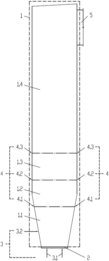
[0025] A high temperature circulating fluidized bed boiler, multi-stage high-efficiency low-nitrogen combustion system includes furnace, air distribution board, primary air inlet and secondary air inlet. The furnace is divided into oxygen-deficient combustion zone, reduction zone, oxidation zone from bottom to top. In the combustion zone and burnout zone, the upper boundary of the oxygen-deficient combustion zone is 4.5 meters away from the surface of the air distribution plate, the upper boundary of the reduction zone is 7.5 meters away from the surface of the air distribution plate, and the upper boundary of the oxidative combustion zone is 9.5 meters away from the surface of the air distribution plate. The exhaustion zone is located above the upper boundary of the oxidative combustion zone. A bottom primary air inlet is arranged under the air distribution plate, a layer of reduction air inlet is arranged on the front and rear walls of the furnace in the reduction zone, and a...

Embodiment 2

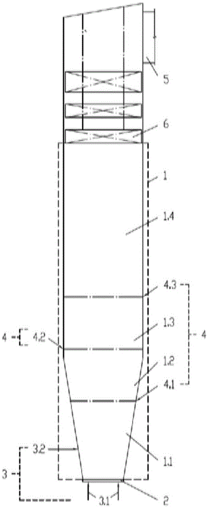
[0034] In this example, in a medium-temperature circulating fluidized bed boiler, the combustion air in the furnace is classified in depth as a whole, and in the height direction of the furnace, according to the combustion characteristics of the fuel, the furnace is divided into oxygen-deficient from bottom to top. combustion zone, reduction zone, oxidative combustion zone and burnout zone.

[0035] The combustion of the fuel in the furnace and the generation and reduction process of nitrogen oxides are basically the same as the embodiment 1, and the difference between the two is:

[0036] In this embodiment, in order to ensure the efficient combustion of the fuel, the height value between the burnout air inlet of the uppermost layer and the first row of pipes on the first group of convection heating surfaces in the upper part of the furnace is set as the average velocity value of the flue gas in the burnout zone. 2.5 times.

[0037] In this embodiment, only one layer of redu...

Embodiment 3

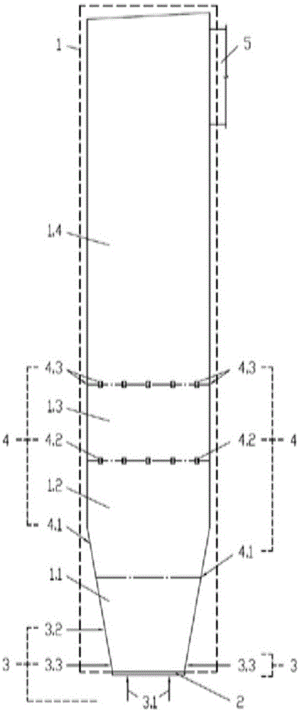
[0040] The overall layout, the combustion of fuel in the furnace, and the generation and reduction process of nitrogen oxides in this embodiment are basically the same as those in Embodiment 1. The differences between the two are:

[0041] In this embodiment, an annular primary air inlet is provided on the furnace wall near the upper part of the air distribution plate.

[0042] In this embodiment, the secondary air enters the furnace in four layers, which are two layers of reducing air, one layer of oxidizing air and one layer of exhaust air. Among them, the vents of the lower reducing air are located on the back wall of the furnace, the vents of the upper reducing air are located on the front wall of the furnace; the vents of the oxidizing air are located on the walls on both sides of the furnace; the vents of the exhausted air are located on the four walls of the furnace.

[0043] In this embodiment, the excess air coefficient of the oxygen-deficient combustion zone is contr...


PUM


Abstract

The invention relates to a multi-grade high-efficiency low-nitrogen combustion method and a multi-grade high-efficiency low-nitrogen combustion system for a circulating fluidized bed boiler. According to the method, combustion air enters a furnace hearth through corresponding inlets respectively to divide the furnace hearth into a less oxygen combustion area, a reduction area, an oxidative combustion area and a burning-out area; the excess air coefficients of each area are respectively controlled to be 0.55-0.95, 0.75-1.15, 1.05-1.25 and greater than or equal to 1.20, so that a fuel is dispersed and uniformly combusted in the furnace hearth. The burning-out area is positioned above the upper boundary of the oxidative combustion area and has the effective height which is not less than 2.5 times of a flue gas average velocity value in the area, the upper boundaries of the remaining areas are respectively 2.0-5.5 meters, 4.5-9.0 meters and 8.0-12.0 meters away from the surface of an air distribution plate. The system which is applicable to the method comprises the furnace hearth, the air distribution plate, a primary air inlet and a secondary air inlet; at least one layer of reducing air inlet, at least one layer of oxidative air inlet and at least one layer of burning-out air inlet are respectively formed in at least one wall of the corresponding area of the furnace hearth. By virtue of the method and the system, the generation capacity of nitrogen oxides can be reduced, and high-efficiency combustion of the fuel can also be realized.

Description

technical field [0001] The invention relates to a boiler combustion method and a combustion system, in particular to a multi-stage high-efficiency low-nitrogen combustion method and a combustion system for a circulating fluidized bed boiler. Background technique [0002] Nitrogen oxide is one of the main pollutants in atmospheric pollution, which endangers human health, affects plant growth, and participates in the destruction of the ozone layer. [0003] Nitrogen oxides mainly come from the direct combustion of solid, liquid and gas fuels. As a major emitter of nitrogen oxides, the control of nitrogen oxides emissions in thermal power plants is very important. In recent years, the low-nitrogen combustion technology to control the formation of nitrogen oxides in the fuel combustion process and the flue gas denitration technology to reduce the nitrogen oxides that have been formed have made great progress. [0004] The low-nitrogen combustion technology can greatly reduce th...

Claims


Application Information

Patent Timeline
Patent Type & Authority Patents(China)
IPC IPC(8): F23C10/00F23C10/18F23C10/20F23L9/00
Inventor 陈勇
Owner 武汉和信益科技有限公司
Why Eureka
Try Eureka