
Metal mesh nested heterojunction organic solar cell and preparation method thereof

A technology of solar cells and metal mesh, applied in circuits, photovoltaic power generation, electrical components, etc., can solve the problems of weak built-in electric field and low conversion efficiency of organic solar cells, achieve strong electron affinity, increase the strength of built-in electric field, increase Effect of Structure Thickness

Inactive Publication Date: 2016-01-27
UNIV OF ELECTRONICS SCI & TECH OF CHINA
View PDF4 Cites 1 Cited by
  • Summary
  • Abstract
  • Description
  • Claims
  • Application Information

AI Technical Summary

Problems solved by technology

[0008] In view of the above-mentioned prior art, the purpose of the present invention is how to provide an organic solar cell with a metal mesh nested heterojunction and its preparation method, so as to solve the problem of low conversion efficiency of the organic solar cell due to the weak built-in electric field at the interface of the heterojunction technical problem

Method used


Image

  • Metal mesh nested heterojunction organic solar cell and preparation method thereof
  • Metal mesh nested heterojunction organic solar cell and preparation method thereof
  • Metal mesh nested heterojunction organic solar cell and preparation method thereof

Examples


Embodiment 1

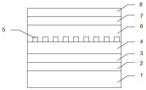
[0043] Device structure such as figure 1 shown. The material and thickness of each layer of the device are as follows: the substrate 1 is glass, the anode electrode 2 is ITO with a thickness of 180nm, and the hole transport layer 3 is copper phthalocyanine CuPc and perfluorophthalocyanine copper F 16 A mixed layer of CuPc with a thickness of 10 nm and a donor material of poly-3-hexylthiophene P 3 HT, the thickness is 30nm, the ultra-thin mesh metal layer is Ag, the thickness of the mesh metal layer is 1nm, the acceptor material is fullerene derivative PC61BM, the thickness is 40nm, the electron buffer layer is 4,7-diphenyl O-phenanthroline Bphen, the thickness is 2.5nm, the cathode is Ag, the thickness is 150nm.

[0044] Its preparation method is as follows:

[0045] ①Use detergent, acetone solution, deionized water and ethanol solution to ultrasonically clean the glass substrate on which the transparent anode electrode ITO has been sputtered, and dry it with dry nitrogen a...

Embodiment 2

[0053] Device structure such as figure 1 shown. The material and thickness of each layer of the device are as follows: the substrate 1 is glass, the anode electrode 2 is ITO with a thickness of 180nm, and the hole transport layer 3 is copper phthalocyanine CuPc and perfluorophthalocyanine copper F 16 A mixed layer of CuPc with a thickness of 10 nm and a donor material of poly[[9-(1-octylnonyl)-9H-carbazole-2,7-diyl]-2,5-thiophenediyl-2,1, 3-benzothiadiazole-4,7-diyl-2,5-thiophenediyl] (PCDTBT), the thickness is 30nm, the ultra-thin mesh metal layer is Au, the thickness of the metal layer is 1nm, the acceptor material It is a fullerene derivative PC71BM with a thickness of 40nm, an electron buffer layer of 4,7-diphenyl-phenanthroline (Bphen) with a thickness of 2.5nm, and a cathode of Ag with a thickness of 150nm. The preparation process is similar to Example 1.

experiment example 3

[0055] Device structure such as figure 1 shown. The material and thickness of each layer of the device are: substrate 1 is glass, anode electrode 2 is ITO with a thickness of 180nm, and hole transport layer 3 is 5,5'-bis(4-biphenyl)-2,2'- A mixed layer of dithiophene (BP2T) and perfluorophthalocyanine copper (F16CuPc) with a thickness of 10 nm, a donor material of poly-3hexylthiophene (P3HT) with a thickness of 30 nm, and an ultra-thin metal layer of Pt with a thickness of 1 nm, The acceptor material is fullerene derivative PC61BM with a thickness of 40nm, the electron buffer layer is 4,7-diphenyl-phenanthroline (Bphen) with a thickness of 2.5nm, and the cathode is Ag with a thickness of 150nm. The preparation process is similar to Example 1.


PUM


Abstract

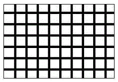
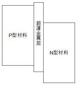
The invention discloses an organic solar cell with a metal mesh nested heterojunction and a preparation method thereof, which relates to the field of organic solar cells, including a transparent substrate, a transparent anode electrode, a hole transport layer, a donor material layer, an ultra-thin The mesh metal layer, the acceptor material layer, the electron buffer layer and the cathode electrode are located between the donor material layer and the acceptor material layer with a mesh-shaped continuous metal mesh nesting layer. The metal mesh layer can form a local Schottky junction with the N-type acceptor material layer. On the basis of the original heterojunction, a double built-in electric field is formed, which is conducive to the stepwise diffusion of electrons from the n-type material to the p-type material. Holes diffuse from p-type materials to n-type materials, increasing the thickness of the heterojunction structure, improving the separation efficiency of photogenerated excitons, and ultimately improving the conversion efficiency of organic solar cells.

Description

technical field [0001] The invention relates to the field of organic solar cells, in particular to an organic solar cell based on a Schottky junction-based metal mesh nested heterojunction and a preparation method thereof. Background technique [0002] With the gradual depletion of fossil resources such as coal and oil, the energy crisis is getting closer and closer to us as time goes by, so finding new energy sources has become a very urgent matter. Compared with solar energy, it is inexhaustible and inexhaustible, and it also has many advantages such as environmental protection, safety, long-term, huge, etc. It has become the most ideal emerging renewable energy known so far. At present, various countries are actively researching and developing new technologies of solar energy, and strive to make breakthroughs in this area. How to better break through this technology has become a matter of strategic significance. [0003] China is the world's largest producer of inorganic...

Claims


Application Information

Patent Timeline
Patent Type & Authority Patents(China)
IPC IPC(8): H01L51/42H01L51/48
CPCH10K71/00H10K85/00H10K30/20Y02E10/549H10K30/35
Inventor 钟建秦春伟杜新炜赵志宇邓鸣于军胜
Owner UNIV OF ELECTRONICS SCI & TECH OF CHINA
Learn More