Spinning process of spinning machine with yarn twisting function

A spinning process and spinning machine technology, applied in the field of new spinning processes, can solve the problems of reducing product quality, increasing energy consumption, reducing efficiency, etc., to control drying temperature and time, to facilitate maintenance and worker operations, to avoid The effect of increased energy consumption

Inactive Publication Date: 2014-03-19
YIBIN GRACE GROUP CO LTD +1
View PDF15 Cites 0 Cited by
  • Summary
  • Abstract
  • Description
  • Claims
  • Application Information

AI Technical Summary

Problems solved by technology

[0009] Disadvantages: low spinning speed, high post-processing costs, and increased production costs
[0012] Disadvantages: Since the silk sliver is washed and dried immediately, the strength of the sliver is low, the whiteness is low, the sliver is rough, and the quality is not as good as that of the semi-continuous spinning machine; in order to increase the sizing of the silk sliver, the sizing needs to be removed when the embroidery thread is dyed. Increase the production cost of downstream products; high quality requirements for raw materials (viscose)
[0021] 1. The above structure limits the length of the roller. The time for the viscose filament to walk on the roller is short, and the forming time of the viscose filament is short. If the spinning speed is to be increased, the reaction time of the viscose filament will inevitably be insufficient and the product quality will be reduced. , so the efficiency of the traditional semi-continuous spinning machine is reduced;
[0022] 2. In order to improve efficiency, multiple filaments are usually processed at the same time, but when multiple viscose filaments are wound on the existing spinning roller, they are easy to twist, causing the viscose filaments to break and affecting the viscose filaments. product quality;
[0024] 4. All the spinning rollers are fixed at one end, which will inevitably require an extremely complex transmission mechanism to drive the rotation of the spinning rollers, which will also lead to an increase in the failure rate, and when changing the type of silk yarn and changing the rotation speed, it is necessary to stop the machine. Then replace the gears in the transmission system, which reduces the production efficiency and increases the production cost
The above-mentioned utility model is a continuous spinning machine, which is equipped with a drying device, and the dried filaments are directly formed into a tube, and the tube forming device is located outside the drying device, but since the spinning roller integrates de-drawing, washing The structure of deacidification, drying and oiling makes the structure of the whole machine complex and increases energy consumption
[0032] To sum up, in the existing spinning process, the winding device of the semi-continuous spinning machine is located below the spinning roll. Since the spinning roll has water and acidic solution dripping, the winding device is easily damaged by spinning. Contamination of water and acidic solution dripping from the spinning roll; and in the existing spinning process using a continuous spinning machine, in order to finally obtain a tube of dry filament, the spinning roll integrates drafting, washing The structure of deacidification, drying and oiling makes the structure of the whole machine complex and increases the energy consumption in the spinning process. In addition, drying on the spinning roller makes it difficult to accurately control the moisture content of the filaments. Filaments from spinning are processed differently, so there is no control over obtaining filaments suitable for various subsequent steps

Method used


Image

  • Spinning process of spinning machine with yarn twisting function
  • Spinning process of spinning machine with yarn twisting function
  • Spinning process of spinning machine with yarn twisting function

Examples


Embodiment 1

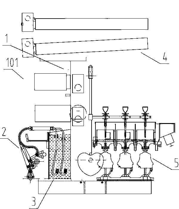
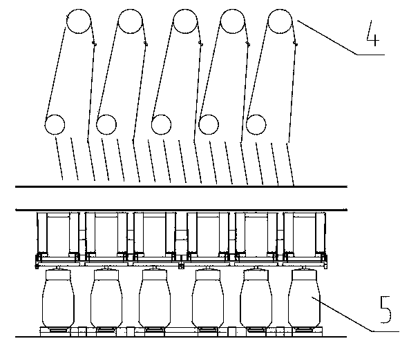
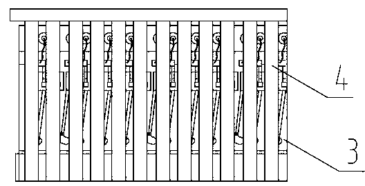
[0113] A spinning process of a spinning machine with twisting function, comprising glue supply, filament forming, spinning and twisting, the glue supply is completed by the glue supply device 2, and the filament forming is completed by the filament Forming device 3 completes, and described spinning is completed by spinning device 4, and described twisting is completed by twisting device 5, and described spinning device 4 comprises many spinning rollers, and the described spinning roller Both ends are fixed, an independent drying and drafting roll 404 is arranged between the spinning rolls in the spinning device 4, and the forming part of the twisting device 5 is located between the wallboards 6 on both sides of the frame 1 The outside of the area, the other side opposite to the spinning surface 101, the spinning surface 101 refers to the outside of the frame 1 wallboard 6, the area where the filament forming device 3 is arranged, and the other side opposite to the area Referre...

Embodiment 2

[0115] A spinning process of a spinning machine with twisting function, comprising glue supply, filament forming, spinning and twisting, the glue supply is completed by the glue supply device 2, and the filament forming is completed by the filament Forming device 3 completes, and described spinning is completed by spinning device 4, and described twisting is completed by twisting device 5, and described spinning device 4 comprises many spinning rollers, and the described spinning roller Both ends are fixed, an independent drying and drafting roll 404 is arranged between the spinning rolls in the spinning device 4, and the forming part of the twisting device 5 is located between the wallboards 6 on both sides of the frame 1 The outside of the area, the other side opposite to the spinning surface 101, the spinning surface 101 refers to the outside of the frame 1 wallboard 6, the area where the filament forming device 3 is arranged, and the other side opposite to the area Referre...

Embodiment 3

[0121] A spinning process of a spinning machine with twisting function, comprising glue supply, filament forming, spinning and twisting, the glue supply is completed by the glue supply device 2, and the filament forming is completed by the filament Forming device 3 completes, and described spinning is completed by spinning device 4, and described twisting is completed by twisting device 5, and described spinning device 4 comprises many spinning rollers, and the described spinning roller Both ends are fixed, an independent drying and drafting roll 404 is arranged between the spinning rolls in the spinning device 4, and the forming part of the twisting device 5 is located between the wallboards 6 on both sides of the frame 1 The outside of the area, the other side opposite to the spinning surface 101, the spinning surface 101 refers to the outside of the frame 1 wallboard 6, the area where the filament forming device 3 is arranged, and the other side opposite to the area Referre...


PUM

PropertyMeasurementUnit
lengthaaaaaaaaaa
lengthaaaaaaaaaa
lengthaaaaaaaaaa

Abstract

The invention relates to a spinning process of a spinning machine with a yarn twisting function. The spinning process comprises glue feeding, strand forming, spinning and yarn twisting. Independent drying traction rollers are arranged between spinning rollers during spinning, forming portions of yarn twisting devices are located on the outer side of the area between wallboards on the two sides of a machine frame and the side opposite to the spinning face, strands obtained after glue feeding, strand forming and spinning pass through the drying traction rollers and then pass through the yarn twisting devices, yarn twisting is finished and embroidery threads are obtained. The spinning machine is provided with the yarn twisting devices, the strands pass through the drying traction rollers of a spinning device for heating and drying and then enter the yarn twisting devices, the strands are processed through the yarn twisting devices, and finished products of the embroidery threads are obtained. High integration of the processes from glue feeding to forming of the embroidery threads is achieved, complication caused by the fact that multiple independent devices are used is avoided, the structure of the whole device is simplified, energy consumption of the device is reduced, production time is saved, and the production efficiency of the embroidery threads is improved.

Description

technical field [0001] The invention relates to a novel spinning process, more specifically, the invention relates to a spinning process of a spinning machine with a twisting function, which belongs to the technical field of spinning. Background technique [0002] Pure methyl cellulose is extracted from cellulose raw material, called pulp. Treat with caustic soda and carbon disulfide to obtain orange-yellow cellulose xanthate sodium, and then dissolve it in dilute sodium hydroxide solution to become viscous spinning stock solution, called viscose. After the viscose is filtered, matured and defoamed, it is wet-spun, and the coagulation bath is composed of sulfuric acid, sodium sulfate and zinc sulfate. Sodium cellulose xanthate in the viscose reacts with sulfuric acid in the coagulation bath to decompose, and the cellulose is regenerated and precipitated. The obtained cellulose fiber becomes viscose fiber after washing, desulfurization, bleaching and drying. Viscose filamen...

Claims


Application Information

Patent Timeline
Patent Type & Authority Applications(China)
IPC IPC(8): D01D13/02D01F2/06D01D1/06D01D10/06D01D5/06D01D5/16
Inventor 冯涛廖周荣孙毅何大雄徐发祥刘志军黄金洪廖秀
Owner YIBIN GRACE GROUP CO LTD
Why Eureka
Try Eureka