
Laser radar detecting light source divergence angle measuring device and method

A laser radar and measurement device technology, which is applied in the direction of measurement devices, radio wave measurement systems, and optical performance testing, can solve problems such as large spot diameter, weak light intensity, and large insertion loss, and achieve high measurement accuracy, simple method, and small error effect

Active Publication Date: 2014-03-19
HEFEI INSTITUTES OF PHYSICAL SCIENCE - CHINESE ACAD OF SCI
View PDF7 Cites 18 Cited by
  • Summary
  • Abstract
  • Description
  • Claims
  • Application Information

AI Technical Summary

Problems solved by technology

[0006] However, at present, in published patents or documents, there is no report on the device and method for measuring the divergence angle of the laser radar to detect the light source. The measurement of the light source divergence angle of the instrument mainly includes photodetector measurement method and CCD imaging method, such as a Chinese invention patent CN1180232C (authorized announcement date is December 15, 2004) laser beam divergence angle of the Institute of Optoelectronic Technology, Chinese Academy of Sciences The test method, which uses a CCD camera to measure the entire two-dimensional light intensity distribution of the focused spot of the laser beam, and then takes the one-dimensional light intensity distribution in the required measurement direction as required, and reduces the light intensity to the maximum value of 1 / e 2 (ie 0.136) The size of the envelope at the start and end of the curve is used as the spot diameter of the laser beam at the second position
This method is not applicable to the measurement of the divergence angle of the laser radar detection light source. First, the laser radar detection light source is collimated and expanded. Strong down to max 1 / e 2 (ie 0.136)" is defined as the spot diameter method, which cannot accurately determine the spot diameter; secondly, the spot diameter of the laser radar detection light source is relatively large, and the spot is generally between 20mm-400mm directly. This method uses CCD to measure the light intensity distribution. It will be limited by the area of ​​the CCD detection panel, and cannot measure large light spots
Another invention patent CN100354621C (authorized announcement date is December 12, 2007) laser divergence angle measuring instrument and measuring method of the Institute of Semiconductors, Chinese Academy of Sciences, the invention describes a measuring method mainly applied to the outgoing beam of semiconductor lasers, The optical fiber head is used to measure the light field intensity, the detection range is small, and the laser spot with a small diameter can be measured; during the measurement process, the moving laser measuring fiber is fixed
This method is also not applicable to the measurement of the divergence angle of the laser radar detection light source. First, the light intensity of the laser radar detection light source beam is weak after being expanded, and the coupling efficiency of the fiber optic probe is low, and the insertion loss is large, so there is very little coupling into the optical fiber. The light intensity cannot be detected; two, the device and method cannot be used for the measurement of larger spot divergence angles

Method used


Image

  • Laser radar detecting light source divergence angle measuring device and method
  • Laser radar detecting light source divergence angle measuring device and method
  • Laser radar detecting light source divergence angle measuring device and method

Examples


Embodiment Construction

[0027] The present invention will be further described below in conjunction with the accompanying drawings and specific embodiments.

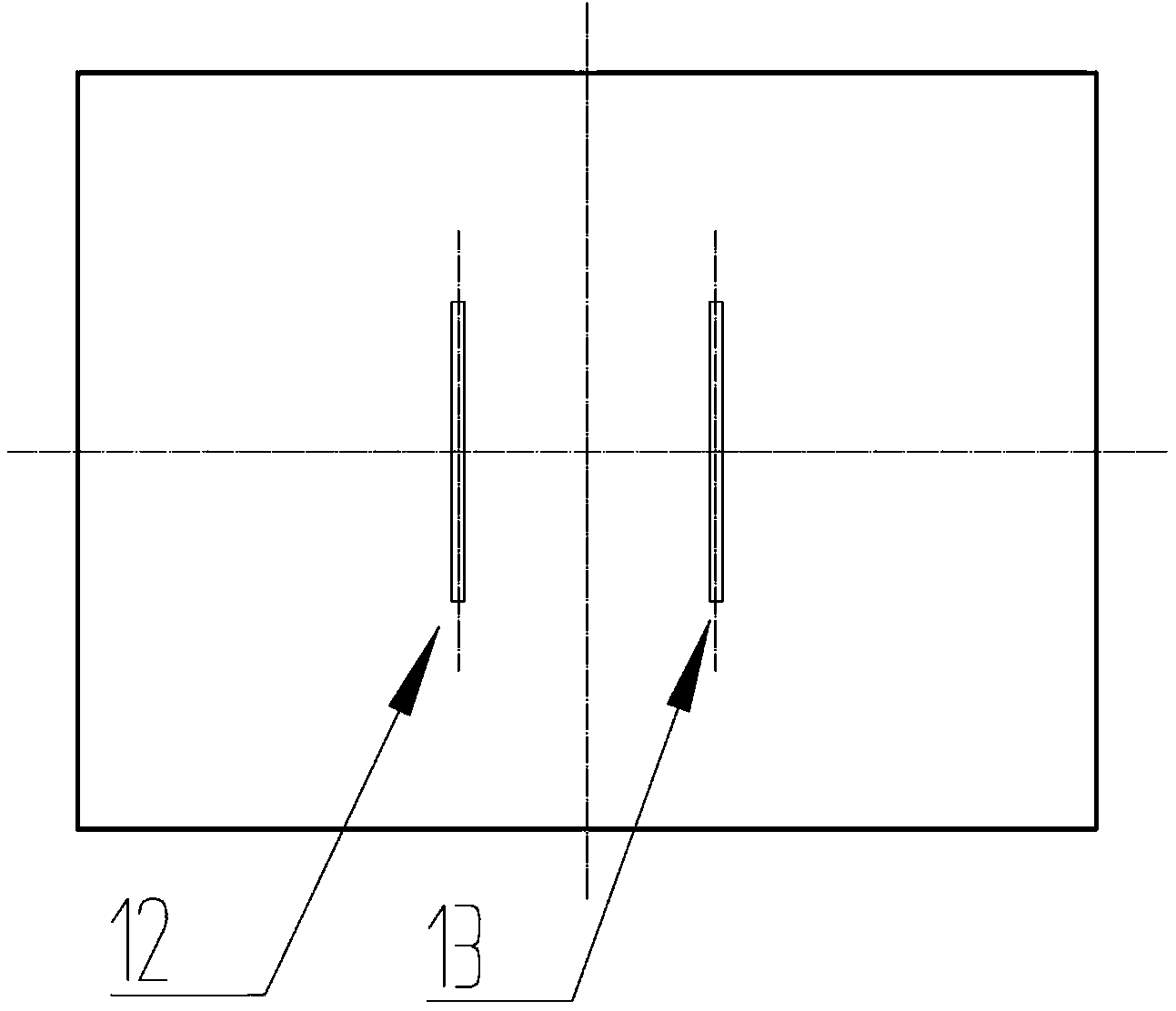
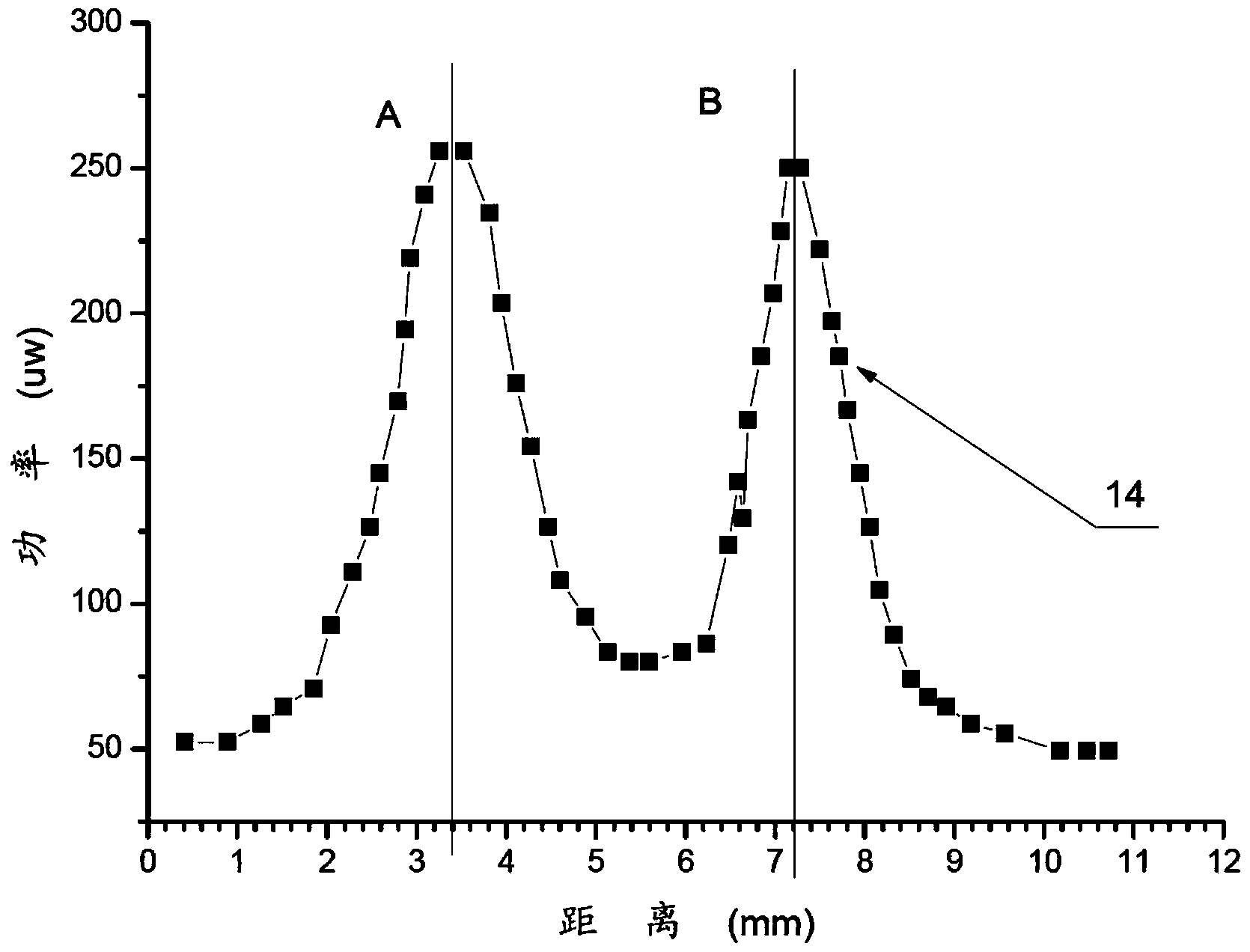
[0028] Such as figure 1 As shown, the laser radar detection light source divergence angle measuring device and method of the present invention are mainly composed of a detection light source 1, an optical lifting platform 2, a collimating telescope 3, a liftable optical adjustment frame-4, an adjustable double slit diaphragm 5, and a The lifting optical adjustment frame 2 is composed of 6, aperture 7, high-precision translation platform 8, and optical power meter 9, and the components are fixed on the measurement platform 10 in sequence; the detection light source 1 is horizontally installed on the lifting optical adjustment frame 1 4, The height is adjustable, and the optical upgrading platform 2 is adjusted so that the light beam emitted by the detection light source 1 is emitted along the system central optical axis 11; The optical adjustme...


PUM

PropertyMeasurementUnit
Diameteraaaaaaaaaa

Abstract

The invention discloses a laser radar detecting light source divergence angle measuring device and method which is mainly applied to the adjustment process of a laser radar launch system and used for performing measurement and adjustment on detecting light divergence angles after beam expansion. The laser radar detecting light source divergence angle measuring device is mainly formed by a detecting light source, an optical lifting platform, a collimating telescope, a lifting optical adjustment frame, a tunable double-slit diaphragm, a diaphragm, a high precision translation platform, an optical power meter and the like. The laser radar detecting light source divergence angle measuring device is provided with the double-slit diaphragm, emission beams of a detected light source are shaped into double beams through the double-slit diaphragm, and accordingly the divergence angles of the beams can be measured only through the measurement of the dispersion degree of the double beams, the integral light spot and light intensity distribution does not need to be measured, and accordingly the measurement on the divergence angles of the different diameters of laser radar detecting light source beams can be achieved. According to the laser radar detecting light source divergence angle measuring device and method, the measurable minimum beam diameter is 2 mm, the measurable maximum beam diameter is 400 mm, and accordingly the measurement on the 0.01 mrad beam divergence angle can be achieved.

Description

technical field [0001] The invention relates to a laser radar optical measurement and correction device, in particular to a laser radar detection light source divergence angle measurement device and method to realize the laser radar detection light source adjustment. Background technique [0002] Lidar uses laser as the detection light source to detect atmospheric particles through the interaction between laser and the atmosphere. The light wave interacts with the medium in the atmosphere to produce a radiation signal containing information about gas molecules and aerosol particles, from which information about gas molecules and aerosol particles can be obtained by using the inversion method. Therefore, the technical basis of lidar is various physical processes generated by the interaction between optical radiation and molecules in the atmosphere and aerosol particles. The role of lidar is an important optical remote sensing detection method, which can realize the detection...

Claims


Application Information

Patent Timeline
IPC IPC(8): G01S7/497
CPCG01M11/02G01S7/497G01S17/95
Inventor 董云升张天舒陆亦怀刘建国刘文清赵南京范广强
Owner HEFEI INSTITUTES OF PHYSICAL SCIENCE - CHINESE ACAD OF SCI
Learn More