Organic light-emitting device and preparation method thereof
An electroluminescent device, an organic technology, applied in the direction of electric solid-state devices, semiconductor/solid-state device manufacturing, electrical components, etc.
- Summary
- Abstract
- Description
- Claims
- Application Information
AI Technical Summary
Problems solved by technology
Method used
Image

Examples
preparation example Construction
[0069] In another aspect, the present invention provides a method for preparing an organic electroluminescent device, comprising the following steps:
[0070] Prepare the functional layer, light-emitting layer and cathode on the anode substrate;
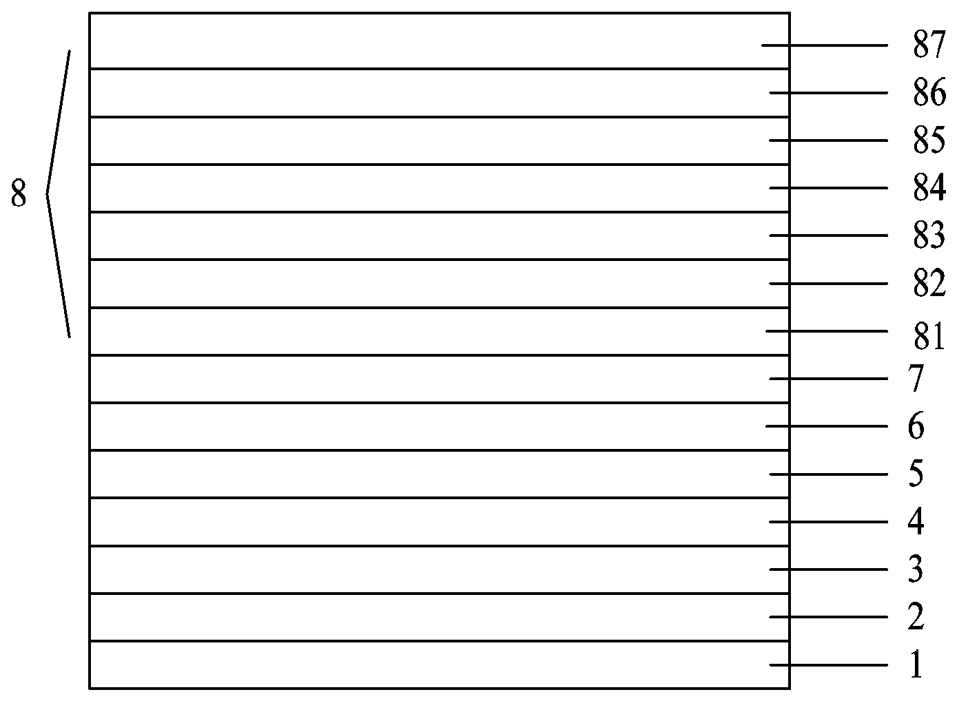
[0071] Evaporate an organic material film layer on the surface of the cathode by vacuum evaporation, and then prepare a thermal buffer layer and an inorganic material film layer sequentially on the organic material film layer by magnetron sputtering, and finally on the inorganic material film layer A polyethylene terephthalate film layer is arranged on the surface of the material film layer to form an encapsulation layer;
[0072] Apply ultraviolet glue on the edge of the polyethylene terephthalate film, dry and harden the ultraviolet glue by ultraviolet curing, seal and form a closed space, and accommodate the functional layer, luminescent layer and cathode in the In the closed space mentioned above, an organic electroluminescent d...
Embodiment 1
[0097]A method for preparing an organic electroluminescent device, comprising the following steps:
[0098] (1) Preparation of functional layer, light-emitting layer and cathode on the anode substrate
[0099] a. Pretreatment of conductive glass substrate
[0100] Take the ITO glass substrate, wash with acetone → ethanol → deionized water → ethanol in sequence, all of them are cleaned with an ultrasonic cleaner, and the single washing is cleaned for 5 minutes, then blown dry with nitrogen, and dried in an oven for later use; The final ITO glass is subjected to surface activation treatment to increase the oxygen content of the conductive surface layer and improve the work function of the conductive layer surface; the thickness of ITO is 100nm;
[0101] b. Preparation of functional layer, light-emitting layer and cathode
[0102] A hole injection layer, a hole transport layer, a light-emitting layer, an electron transport layer and an electron injection layer are sequentially ...
Embodiment 2
[0119] A method for preparing an organic electroluminescent device, comprising the following steps:
[0120] (1) Preparation of functional layer, light-emitting layer and cathode on the anode substrate
[0121] With embodiment one;
[0122] (2) Prepare the encapsulation layer on the cathode
[0123] A 250nm NPB film was prepared on the surface of the cathode by vacuum evaporation as an organic material film layer, and the vacuum degree was controlled at 5×10 -5 Pa, the evaporation rate is
[0124] A thermal buffer layer with a thickness of 120nm was prepared on the surface of the NPB film by magnetron sputtering, and the SiO 2 As a target, the background vacuum is controlled to 5×10 -5 Pa, into the argon, the flow rate is 8sccm;
[0125] In SiO 2 On the surface of the thermal buffer layer, an inorganic material film with a thickness of 100 nm was prepared by magnetron sputtering, and MoO 3 and SiO as the target material, the mass ratio of SiO is 30%, and the backgroun...
PUM
| Property | Measurement | Unit |
|---|---|---|
| Thickness | aaaaa | aaaaa |
| Thickness | aaaaa | aaaaa |
| Thickness | aaaaa | aaaaa |
Abstract
Description
Claims
Application Information
 - R&D
- Intellectual Property
- Life Sciences
- Materials
- Tech Scout
- Unparalleled Data Quality
- Higher Quality Content
- 60% Fewer Hallucinations
Browse by: Latest US Patents, China's latest patents, Technical Efficacy Thesaurus, Application Domain, Technology Topic, Popular Technical Reports.
© 2025 PatSnap. All rights reserved.Legal|Privacy policy|Modern Slavery Act Transparency Statement|Sitemap|About US| Contact US: help@patsnap.com