Eureka AIR delivers breakthrough ideas for toughest innovation challenges, trusted by R&D personnel around the world.

CO2 gas coke chemical-looping combustion power generating system and method

A chemical looping combustion and power generation system technology, applied in the field of CO2 gasification coke chemical looping combustion power generation system, can solve the problems of high investment, high energy consumption, low initial temperature of gas turbine inlet, etc., to reduce system energy consumption, solve High energy consumption and high cost, reducing the effect of irreversible loss

Active Publication Date: 2014-04-30
INST OF ENGINEERING THERMOPHYSICS - CHINESE ACAD OF SCI
View PDF3 Cites 27 Cited by
  • Summary
  • Abstract
  • Description
  • Claims
  • Application Information

AI Technical Summary

Problems solved by technology

[0007] In view of this, the purpose of the present invention is to propose a CO 2 A chemical chain combustion power generation system and method for gasifying coke to solve the problems of high energy consumption and high investment caused by the need to add air separation units in traditional coal gasification power generation systems, and at the same time capture CO at low cost and low energy consumption 2 , and recycle it, and improve the low initial temperature of the gas turbine inlet caused by the restriction of the circulating material in the chemical looping combustion power system

Method used

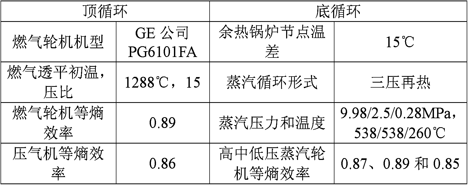

Image

  • CO2 gas coke chemical-looping combustion power generating system and method
  • CO2 gas coke chemical-looping combustion power generating system and method
  • CO2 gas coke chemical-looping combustion power generating system and method

Examples


Embodiment Construction

[0060] In order to make the object, technical solution and advantages of the present invention clearer, the present invention will be described in further detail below in conjunction with specific embodiments and with reference to the accompanying drawings.

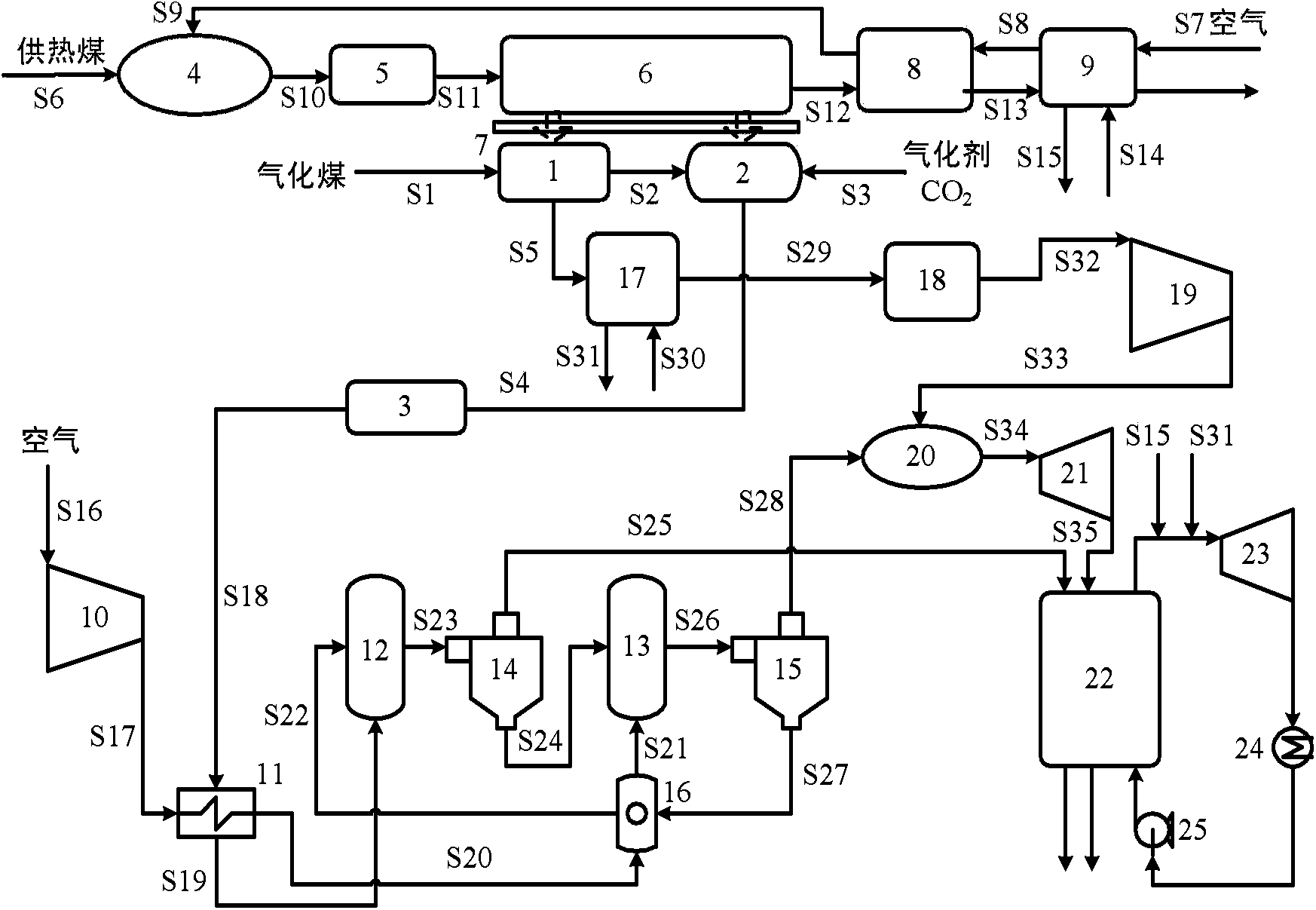
[0061] Such as figure 1 as shown, figure 1 is the CO according to the embodiment of the present invention 2 Schematic diagram of a chemical looping combustion power generation system for gasified coke. Among them, 1 is a carbonization chamber, 2 is a gasification chamber, 3, 5, and 18 are dust removal chambers, 4 is a coal combustion chamber, 6 is a heat transfer chamber, 7 is a partition wall, 8 is a regenerative heat exchanger, 9, 17 is a waste heat boiler, 10 is a compressor, 11 is a heat exchanger, 12 is a reduction reactor, 13 is an oxidation reactor, 14 and 15 are cyclone separators, 16 is a gas-solid heat exchanger, 19 is a gas compressor, 20 is a supplementary combustion combustion chamber, 21 is a gas turbine,...


PUM


Abstract

The invention discloses a CO2 gas coke chemical-looping combustion power generating system and method. The system comprises a coal step gasification subsystem, a fire coal heating subsystem, a chemical-looping combustion subsystem and a power generating subsystem. According to the system and method, coal to be gasified is partially gasified through the carbonization process, coke oven gas and coarse coke are generated, then the coarse coke reacts with CO2 to generate CO, and therefore step gasification of hydrogen and carbon components of the coal is realized, moreover, an expensive air separating unit is omitted, and the system energy consumption is lowered; through chemical-looping combustion of the CO, losses in the combustion process is reduced, and the efficiency of the system is improved; through afterburning of the coke oven gas, energy waste of the coke oven gas is avoided, the temperature of a fuel gas turbine inlet is lowered, and the problem that in a chemical-looping combustion power system, due to circulation material limitation, the primary temperature of a fuel gas turbine inlet is low is solved. Due to the fact that CO2 generated in a chemical-looping combustion reduction reactor is not diluted by N2, CO2 zero-energy-consumption separation can be realized by removing steam through simple condensing.

Description

technical field [0001] The invention relates to the technical field of gasification and power generation, in particular to a CO 2 A chemical looping combustion power generation system and method for gasified coke. Background technique [0002] China is a country where coal is the main primary energy source, and its coal output ranks first in the world. In my country, coal is widely used in a relatively extensive way, and is generally burned directly as fuel for heating or power generation. However, the existing direct coal-fired steam power cycle power generation system mainly has many problems such as low efficiency, serious pollution, and large water consumption. It is bound to hinder the sustainable development of our country's environment and economy. [0003] Compared with coal-fired power plants, integrated gasification combined cycle (IGCC) has low pollutant emissions, high system cycle efficiency, and is easy to remove greenhouse gas CO more economically on this bas...

Claims


Application Information

Patent Timeline
IPC IPC(8): F01K23/10F02C6/18C10J3/00
CPCY02E20/16Y02E20/18Y02P20/129
Inventor 金红光洪慧张筱松王赵国许璐
Owner INST OF ENGINEERING THERMOPHYSICS - CHINESE ACAD OF SCI
Why Eureka
Eureka Blog
Learn More