
Liquid slag granulation and waste heat dry process fluidization high-grade cascaded recycling method and liquid slag granulation and waste heat dry process fluidization high-grade cascaded recycling system

A cascade recovery, liquid slag technology, applied in the direction of recycling technology, heat exchanger types, lighting and heating equipment, etc., can solve the problems of not really realizing industrialization, the waste heat resources are not utilized, and stay, and improve the utilization of waste heat. The effect of grade and utilization efficiency, improving the utilization level of industrial waste heat, and good promotion and application value

Inactive Publication Date: 2014-05-07
GUANGZHOU INST OF ENERGY CONVERSION - CHINESE ACAD OF SCI
View PDF2 Cites 8 Cited by
  • Summary
  • Abstract
  • Description
  • Claims
  • Application Information

AI Technical Summary

Problems solved by technology

The disadvantages of this technology include: (1) Waste heat resources are not utilized, high-grade heat energy is directly cooled into low-grade heat energy, and a large amount of heat energy is wasted
About 1 ton of water is consumed per ton of blast furnace slag, which is especially problematic in regions with severe water shortages
(3) Pollution of the environment
A large amount of H2S and SO are produced in the process of water quenching slag x Discharged into the atmosphere with water vapor, causing environmental pollution
(4) High energy consumption
However, at present, most of them are still in the stage of laboratory research and industrial experiment, and have not really realized industrialization.

Method used


Image

  • Liquid slag granulation and waste heat dry process fluidization high-grade cascaded recycling method and liquid slag granulation and waste heat dry process fluidization high-grade cascaded recycling system
  • Liquid slag granulation and waste heat dry process fluidization high-grade cascaded recycling method and liquid slag granulation and waste heat dry process fluidization high-grade cascaded recycling system
  • Liquid slag granulation and waste heat dry process fluidization high-grade cascaded recycling method and liquid slag granulation and waste heat dry process fluidization high-grade cascaded recycling system

Examples


Embodiment example 1

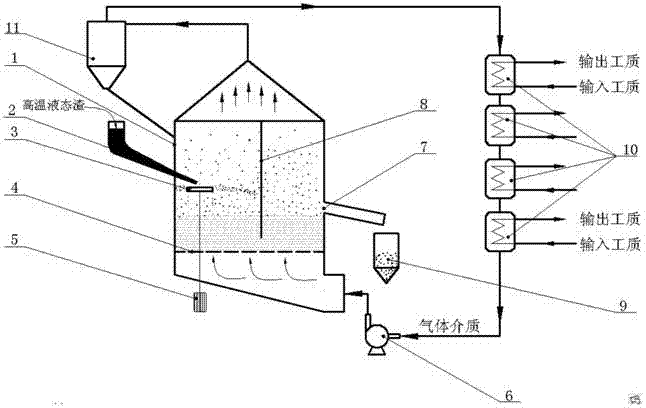
[0043] see figure 1 As shown, a high-grade cascade recovery method for liquid slag granulation and residual heat dry fluidization, including a fluidized bed 1, a high-temperature liquid slag inlet 2, a granulation device 3, an air distribution plate 4, a motor 5, and a fan 6 , Slag particle outlet 7 and dividing plate 8.

[0044] The process flow of high-temperature liquid slag is as follows: the fluidized bed 1 is divided into two connected chambers by a partition plate 8, a liquid slag inlet 2 is opened on one of the chambers, and at least one slag inlet 2 is opened on the other chamber. The high-temperature liquid slag flows into the granulation device 3 in the fluidized bed 1 from the high-temperature liquid slag inlet 2. The motor 5 is connected with the granulation device 3. The granulation device 3 can be a rotating cup. Under the action, the liquid slag is broken and granulated into particles, and the slag particles are fluidized and flow to the slag particle outlet 7...

Embodiment example 2

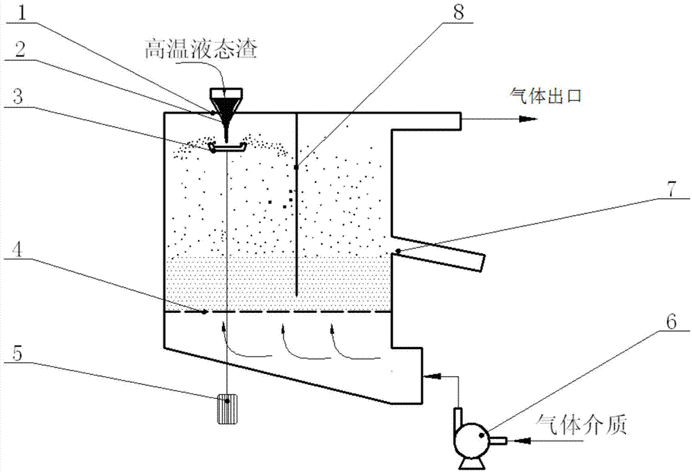
[0051] see figure 2 As shown, the process flow is similar to that of Example 1, the difference is that: (1) The inlet 2 of the high-temperature liquid slag in this example is arranged on the side of the fluidized bed 1 to guide the high-temperature liquid slag to flow obliquely into the fluidized bed; ( 2) The gas outlet is arranged on the top of the fluidized bed 1, and the high-temperature gas medium is discharged from the top of the fluidized bed 1, and a cyclone separator 11 is installed to separate the slag particles from the gas, and the separated slag particles flow back to the fluidized bed 1 for purification The final high-temperature gas transfers heat to other working fluids through several heat exchangers 10. (3) After the heat exchange by the heat exchanger 10, the temperature of the gas is lowered and then sent back to the fan 6 for reuse as the fluidized air circulation in the fluidized bed 1, so as to improve the utilization rate of waste heat.

Embodiment example 3

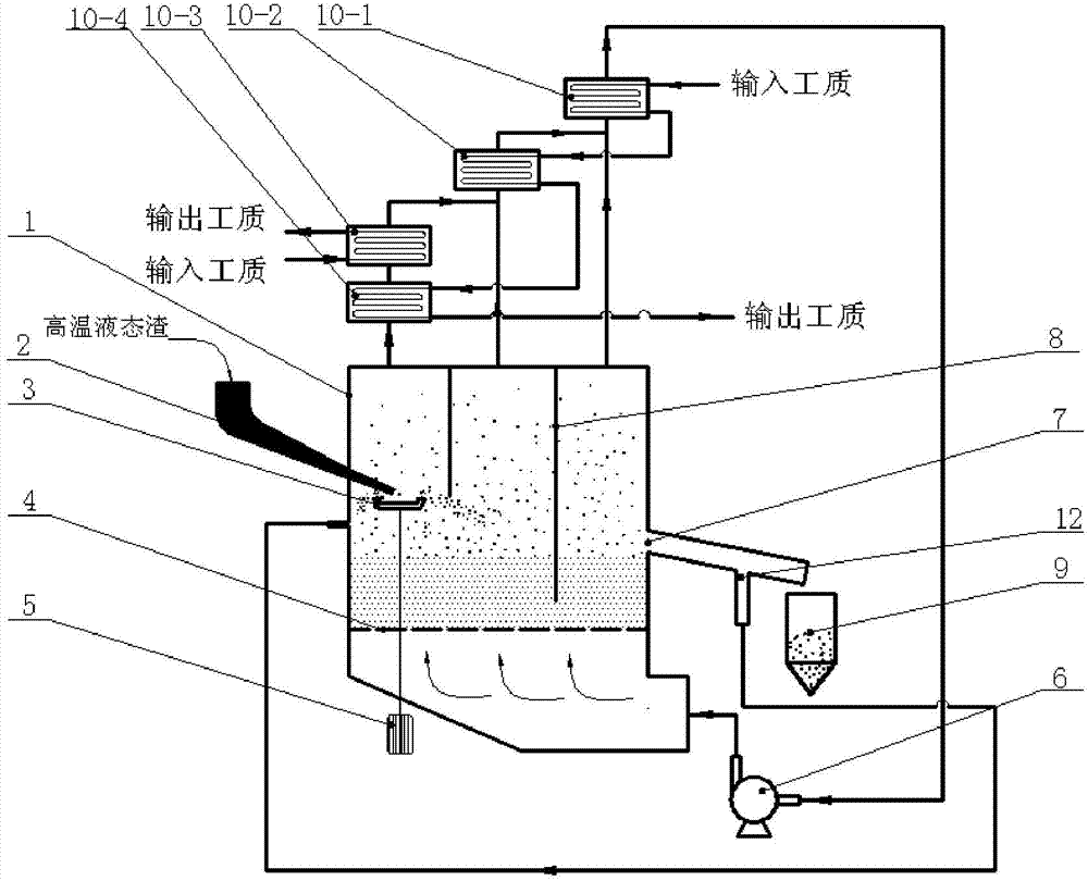
[0053] see image 3 As shown, the process flow is similar to that of Example 2, the difference is: (1) The fluidized bed 1 adopts a multi-chamber fluidized bed structure, and the bed of the fluidized bed 1 is divided into three by two partition plates. In the connected chambers, a high-temperature liquid slag granulation device 3 is installed in the first chamber, a liquid slag inlet 2 is opened in the first chamber, and a slag particle outlet 7 is arranged in the last chamber. (2) Each chamber of the fluidized bed 1 is provided with a gas outlet respectively, and the high-temperature gas after heat exchange with the high-temperature slag particles flows out from the gas outlet of each chamber, instead of mixing gases of different temperatures in each chamber as in the second embodiment . (3) According to the different temperatures of the gas outlets of each chamber, the superheater 10-4, the reheater 10-3, the evaporator 10-2 and the economizer 10-1 are respectively set up t...


PUM


Abstract

The invention discloses a liquid slag granulation and waste heat dry process fluidization high-grade cascaded recycling method and a liquid slag granulation and waste heat dry process fluidization high-grade cascaded recycling system. The liquid slag granulation and waste heat dry process fluidization high-grade cascaded recycling system is characterized in that the inner part of a fluidized bed is divided into at least two communicated cavities, liquid slag flows into the fluidized bed from one of the cavities in a single-point or multiple-point manner; a granulation device for crushing and granulating the liquid slag is arranged in the fluidized bed; a gas medium is fed into the fluidized bed, liquid slag particles subjected to granulation flow in a fluidization manner under the effect of the gas medium in the fluidized bed and transfers heat to the gas medium so as to realize the waste heat recovery of the liquid slag, and the gas medium absorbing the heat of the liquid slag particles outflows from a gas outlet in the fluidized bed. The liquid slag granulation and waste heat dry process fluidization high-grade cascaded recycling method and the liquid slag granulation and waste heat dry process fluidization high-grade cascaded recycling system can further increase the utilization level of industrial waste heat, particularly the recycling level of high-temperature liquid slag energy, and promote energy conservation and emission reduction of national related industries, are in line with national related industry energy conservation and emission reduction policy and have good popularization and application value.

Description

technical field [0001] The invention relates to a high-grade cascade recovery method for liquid slag granulation and waste heat dry fluidization, more specifically, it is a method for granulating high-temperature liquid slag and using fluidization technology to convert the high-temperature waste heat of liquid slag The recycling method and device are energy-saving technologies aimed at utilizing industrial waste heat. Background technique [0002] my country is in the process of industrialization, and a large amount of high-temperature liquid slag is produced in the production process of many industrial industries. Taking the blast furnace ironmaking process as an example, about 300 kg of blast furnace slag is produced per ton of iron produced, and the slag discharge temperature is between 1350 and 1550 °C. Including the heat of fusion and sensible heat, the heat contained in each ton of blast furnace liquid slag is 50-80 kg of standard coal. my country's pig iron production ...

Claims


Application Information

Patent Timeline
IPC IPC(8): C21B3/06C21B3/08C04B5/02F28C3/16
CPCY02W30/50
Inventor 闫常峰郭常青李萍李文博
Owner GUANGZHOU INST OF ENERGY CONVERSION - CHINESE ACAD OF SCI
Learn More