Coke oven waste gas utilization device and application method thereof

A coke oven gas and coke oven technology, applied in the coking field, can solve problems such as large water demand, and achieve the effects of low renovation cost, low construction cost, and sufficient gas-liquid separation

Active Publication Date: 2014-05-21
TAIYUAN UNIV OF TECH
View PDF7 Cites 2 Cited by
  • Summary
  • Abstract
  • Description
  • Claims
  • Application Information

AI Technical Summary

Problems solved by technology

The water can be used as circulating water in the process system through separation, and can also be used as water for coke quenching, which saves external water and solves the problem of large water demand in the coal chemical industry

Method used


Image

  • Coke oven waste gas utilization device and application method thereof

Examples


Embodiment 1

[0028] Example 1: Coke oven waste gas utilization device

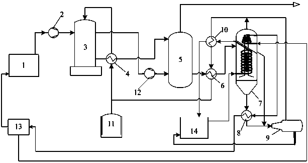
[0029] figure 1 A schematic flow chart of the utilization of coke oven waste gas in the present invention is shown.

[0030] A coke oven waste gas utilization device, comprising a coke oven 1, an air separator 13, a coke oven gas tank 11, a multi-stage gas-liquid separator 7, an expansion flash evaporator 9, a reformer 3, and a chemical synthesizer 5; The furnace 1 is connected to the reformer 3 through the compressor 2, the syngas outlet at the upper end of the reformer 3 is connected to the chemical synthesizer 5 through the booster 12, and the exhaust gas outlet at the lower end of the reformer 3 is connected with the chemical synthesis gas through the mixed gas preheater 4 The product synthesizer 5 is connected; the exhaust gas outlet at the lower end of the chemical synthesizer 5 is connected with a multi-stage gas-liquid separator 7, and the multi-stage gas-liquid separator 7 is a cyclone spiral pipeline heat ex...

Embodiment 2

[0035] Embodiment 2: Coke oven waste gas utilization method

[0036] The specific steps are:

[0037] (1) Heating of exhaust gas and separation of exhaust gas:

[0038] Exhaust gas at 400°C produced by coke oven 1 is pressurized at 10,000 kmol / h by compressor 2 to 3.5MPa and then enters reformer 3. The temperature of the exiting gas drops to 380°C. After heat exchange by mixed gas preheater 4, it enters the chemical Synthesizer 5, inlet 300°C, 3.44MPa, outlet 260°C, 3.42 MPa, then cooled to 200°C by waste gas cooler 6, enters multi-stage gas-liquid separator 7, heat exchange through cyclone spiral tube, bottom outlet temperature 130°C, Pressure 3.38MPa, superheated water 3795.19 kmol / h (including CO 2 6.56 v%) with CO 2 Saturated water vapor (CO 2 Content 31.44 v%) rises from the middle standpipe and enters the top through the conical liquid nitrogen coil, and the outlet temperature at the top drops to 40°C (containing 99.9% CO 2 ), 4253.03 kmol / h H 2 O leads out from t...


PUM


Abstract

The invention discloses a coke oven waste gas utilization device and an application method thereof, and belongs to the technical field of coking. In the device, a coke oven is connected with a reformer through a compressor, a synthesized gas outlet at the upper end of the reformer is connected with a chemical synthesizer through a supercharger, a waste gas outlet at the lower end of the chemical synthesizer is connected with a multi-level gas liquid separator, the multi-level gas liquid separator is a cyclone spiral pipeline heat exchanger, the lower end of the multi-level gas liquid separator leads to an expansion flash vessel, a gas outlet of the expansion flash vessel is connected with the upper end of the reformer, a liquid outlet of the expansion flash vessel leads to a water reservoir, oxygen separated by an air separator leads to the coke oven along a pipeline, and liquid nitrogen separated by the air separator leads to the multi-level gas liquid separator. Firstly the heat of the waste gas and the separated CO2 and water are fully utilized, and in addition, the liquid nitrogen separated by the air separator serves as a condensing medium to cool in the multi-level gas liquid separator. The coke oven waste gas utilization device is a green and environmentally-friendly process unit. The building and construction costs of the device are low, and the device is easy to popularize and apply.

Description

technical field [0001] The invention relates to a coke oven waste gas utilization device and its application method, in particular to a coke oven waste gas CO 2 and water separation device and coke oven exhaust gas heat utilization and CO 2 The system process equipment utilized. It belongs to the technical field of coking. Background technique [0002] From the current perspective of the entire coking industry chain, the coking process and the coke oven gas conversion and utilization process are independent of each other, and the degree of coupling between the production processes is low. Energy resources cannot be fully utilized in the entire production chain process, resulting in the integration of the entire industry chain. The overall energy and element utilization efficiency is low, and nearly half of the coke oven gas is directly burned for self-heating, which emits a large amount of CO 2 , most of the C elements have not been effectively utilized, which greatly was...

Claims


Application Information

Patent Timeline
Patent Type & Authority Applications(China)
IPC IPC(8): F27D17/00C01B3/34
CPCY02P10/122Y02P10/143Y02P10/25
Inventor 张继龙郑华艳张小超荆洁颖易群李刚任龙任晓霞
Owner TAIYUAN UNIV OF TECH
Why Eureka
Try Eureka