
Communication signal source

A communication signal and propagation direction technology, applied in the field of optical communication, can solve the problems of low optical fiber damage threshold, poor tunable performance, unreasonable optical fiber structure, etc.

Inactive Publication Date: 2014-05-21
WUXI CINSEC INFORMATION TECH
View PDF3 Cites 1 Cited by
  • Summary
  • Abstract
  • Description
  • Claims
  • Application Information

AI Technical Summary

Problems solved by technology

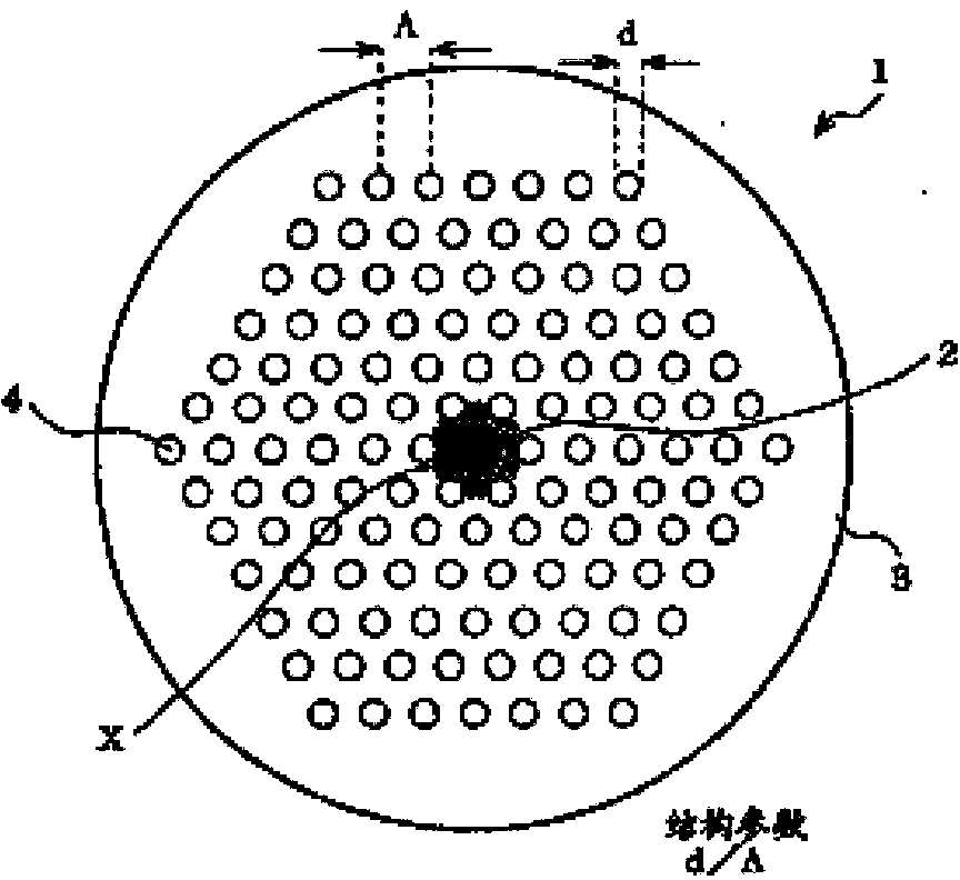
[0008] However, due to the unreasonable structure of photonic crystal fiber, existing photonic crystal fiber lasers generally have the defects of low optical damage threshold, poor tunable performance, and poor optical output quality.

Method used


Image

  • Communication signal source
  • Communication signal source
  • Communication signal source

Examples


Embodiment Construction

[0024] Preferred embodiments of the present invention will be described below with reference to the accompanying drawings. First, use figure 1 A fiber laser using an optical fiber for a fiber laser showing a preferred embodiment of the present invention will be described. Such as figure 1 As shown, this embodiment includes a semiconductor laser diode 1 with a pigtail, a first plano-convex lens 2, a dichroic mirror 3, a second plano-convex lens 4, a double-clad photonic crystal fiber 5, a lens 6, and a filter.

[0025] Such as figure 1 As shown: the laser emitted by the semiconductor laser diode 1 is output through the pigtail 8 with a core diameter of 200 μm and a numerical aperture of 0.22. The maximum LD current of 45A corresponds to a maximum output power of 30W of the 915nm laser. After the light is collimated and focused through the first plano-convex lens 2 with a focal length of 8mm, the dichromatic mirror 3, and the second plano-convex lens 4 with a focal length of ...


PUM


Abstract

The invention relates to a communication signal source, in particular to a photonic crystal fiber laser. The photonic crystal fiber laser comprises a pump light source, an optical coupler and a photonic crystal fiber, wherein the optical coupler enables light emitted by the pump light source to be coupled in the photonic crystal fiber, and light reflection parts are arranged at two ends of the photonic crystal fiber to form an optical resonant cavity. The communication signal source is characterized in that the photonic crystal fiber is provided with a rare earth adding core where rare earth elements are added, a covering layer formed around the rare earth adding core and a plurality of through holes formed on the covering layer. Excitation light enters from the end of the covering layer, the rare earth elements are excited to output high-power laser oscillation light, and the through holes are filled with a liquid material with the dielectric constant ranging from 1.6 to 2.8.

Description

technical field [0001] The invention belongs to the technical field of optical communication, in particular to a communication signal source, in particular to a photonic crystal fiber laser. Background technique [0002] Fiber laser refers to a laser that uses rare earth element-doped glass fiber as the gain medium. Fiber laser can be developed on the basis of fiber amplifier: under the action of pump light, it is easy to form high power density in the fiber, resulting in the laser of the laser working substance. The energy level "particle number inversion", when properly added to the positive feedback loop (to form a resonant cavity), can form a laser oscillation output. [0003] Fiber laser has a wide range of applications, including laser optical fiber communication, laser space long-distance communication, industrial shipbuilding, automobile manufacturing, laser engraving, laser marking, laser cutting, printing roller, metal and non-metal drilling / cutting / welding (brazin...

Claims


Application Information

Patent Timeline
Patent Type & Authority Applications(China)
IPC IPC(8): H01S3/067H01S3/10
Inventor 耿振民
Owner WUXI CINSEC INFORMATION TECH
Learn More