Alternating current-direct current converting circuit and control method thereof
一种直流变换电路、逆变电路的技术,应用在交流功率输入变换为直流功率输出、直流功率输入变换为直流功率输出、不可逆的交流功率输入变换为直流功率输出等方向,能够解决二极管串联损耗大、输出电压电流纹波大、变化等问题,达到减少二极管损耗、降低电压应力和开关损耗、降低电压应力的效果
- Summary
- Abstract
- Description
- Claims
- Application Information
AI Technical Summary
Problems solved by technology
Method used
Image
Examples
Embodiment 1
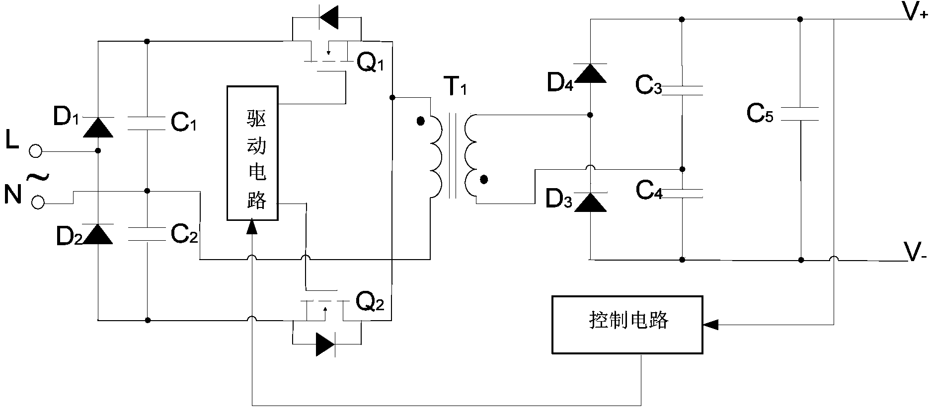
[0030] like figure 1 The shown AC-DC conversion circuit includes input rectification circuit, primary side input filter capacitors C1, C2, primary side inverter circuit, drive circuit, high frequency isolation transformer T1, secondary side rectification circuit, secondary side third and fourth Capacitors C3, C4, secondary output filter capacitor C5, and a control circuit connected between the secondary output filter capacitor C5 and the driving circuit.
[0031] The input rectification circuit includes two input rectification diodes D1 and D2, the anode of the input rectification diode D1 and the cathode of the input rectification diode D2 are connected to the AC input live wire L, and the primary side input filter capacitor includes an AC input neutral line N as the midpoint Two input high-frequency filter capacitors C1 and C2 are connected in series, and the opposite ends of the two input high-frequency filter capacitors C1 and C2 are respectively connected to the positive ...
Embodiment 2
[0065] The invention also provides an AC-DC conversion circuit with two-phase, three-phase or more phase input. like Figure 4 Shown is a three-phase four-wire input AC-DC conversion circuit, the basic circuit composition and beneficial effects are the same as those in Embodiment 1, the difference is that the input is three-phase. The advantage is that in theory, an output voltage with better output voltage characteristics than that of Embodiment 1 can be obtained, the output voltage is smoother, and the ripple voltage is smaller. Figure 4 Among them, D1a, D2a, D1b, D2b, D1c, D2c represent the primary side rectifier diodes, C1a, C2a, C1b, C2b, C1c, C2c represent the primary side filter capacitors, Q1a, Q2a, Q1b, Q2b, Q1c, Q2c represent the primary side Inverter switching tubes, T1a, T1b, T1c represent transformers, D3a, D4a, D3b, D4b, D3c, D4c represent secondary side rectifier diodes, C3a, C4a, C5b, C3b, C4b, C5b, C3c, C4c, C5c represent secondary side filter capacitor.
Embodiment 3
[0067] The invention also provides another two-phase, three-phase or more phase input AC-DC conversion circuit. like Figure 5 Shown is a three-phase three-wire input AC-DC conversion circuit, the basic circuit composition and beneficial effects are the same as those of the second embodiment, the difference is that the input has no neutral line input. The advantage is that the aforementioned performance can still be achieved in the actual three-phase three-wire input environment without neutral line input.
[0068] The circuit of the present invention has two different working modes, forward and reverse, and can realize a larger adjustment range of input and output voltages, and at the same time, the input current can also track the input voltage to realize power factor correction. At the same time, due to the function of the active clamp circuit, it can reduce the reverse recovery voltage peak and switching loss caused by the leakage inductance of the isolation transformer and...
PUM
 Abstract
Description
Claims
Application Information
 - R&D
- Intellectual Property
- Life Sciences
- Materials
- Tech Scout
- Unparalleled Data Quality
- Higher Quality Content
- 60% Fewer Hallucinations
Browse by: Latest US Patents, China's latest patents, Technical Efficacy Thesaurus, Application Domain, Technology Topic, Popular Technical Reports.
© 2025 PatSnap. All rights reserved.Legal|Privacy policy|Modern Slavery Act Transparency Statement|Sitemap|About US| Contact US: help@patsnap.com


