

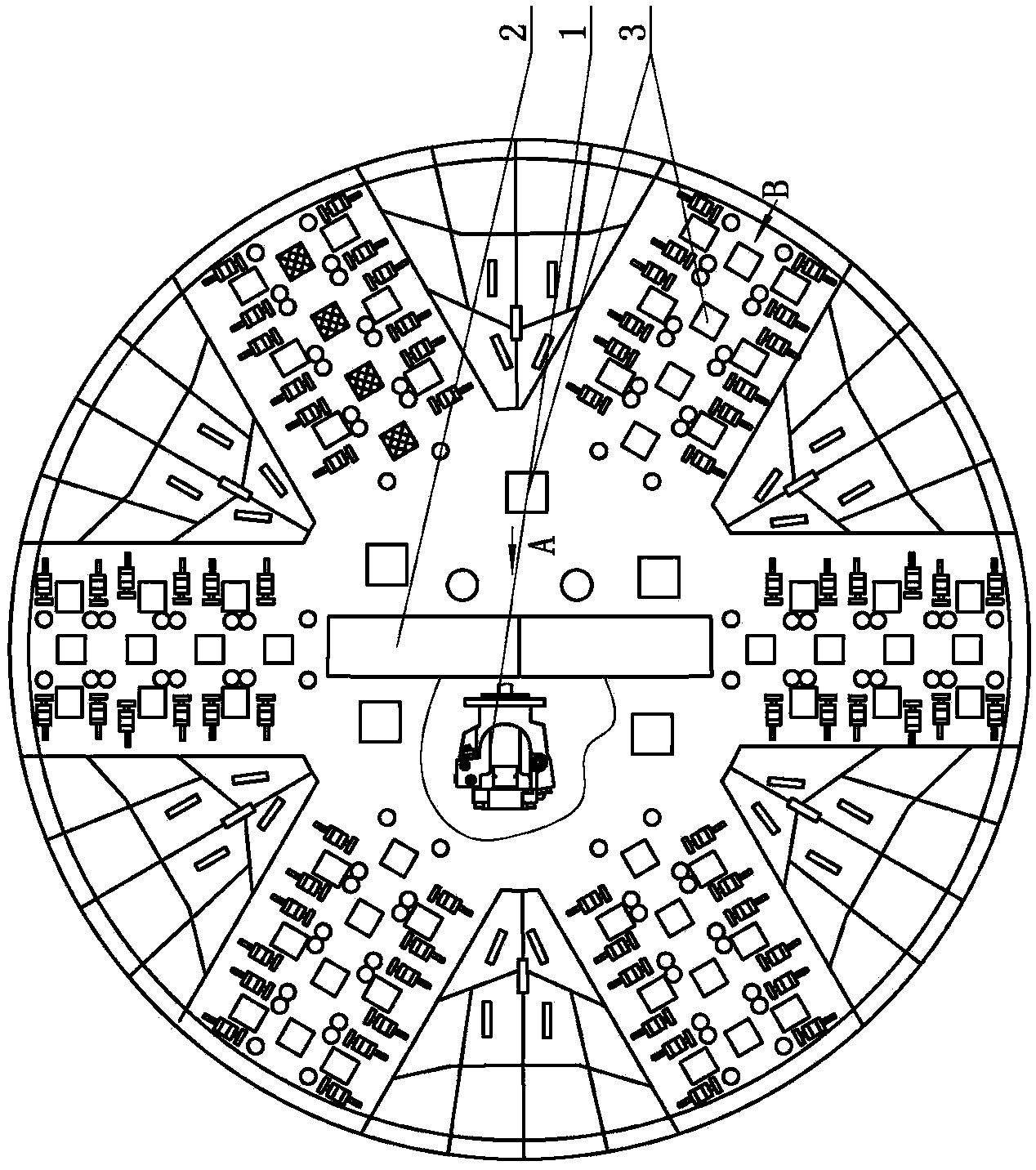
Slurry shield cutter head washing system
A shield cutter head, mud water technology, applied in welding equipment, manufacturing tools, welding/cutting media/materials, etc., can solve the problem that the attachment cannot be washed away, the operation of the cutter arm of the cutter head is blocked, and the work efficiency of the cutter head is reduced. and other problems, to achieve the effect of improving welding process performance, maintaining high efficiency and low manufacturing cost
- Summary
- Abstract
- Description
- Claims
- Application Information
AI Technical Summary
Problems solved by technology
Method used
Image

Examples
Embodiment 1
[0019] Embodiment 1: Ferrovanadium nitride 2g, ferrochromium nitride 3g, ferromanganese nitride 5g, ferro-titanium 5g, tungsten carbide 7g, titanium carbide 10g, cobalt carbide 1g, ferro-tungsten 7g, metal manganese 25g, ferro-boron 5g , monazite powder 3g, nitrocellulose 2g, the balance is metallic iron;
Embodiment 2
[0020] Embodiment two: ferrovanadium nitride 3g, ferrochromium nitride 5g, ferromanganese nitride 2g, ferro-titanium 8g, tungsten carbide 10g, titanium carbide 5g, cobalt carbide 3g, ferro-tungsten 10g, metal manganese 10g, ferro-boron 7g, Monazite powder 5g, nitrocellulose 3g, the balance is metallic iron;
Embodiment 3
[0021] Embodiment three: ferrovanadium nitride 5g, ferrochromium nitride 2g, ferromanganese nitride 4g, ferro-titanium 10g, tungsten carbide 5g, titanium carbide 6g, cobalt carbide 5g, ferro-tungsten 5g, metal manganese 20g, ferro-boron 10g, Monazite powder 1g, nitrocellulose 5g, and the balance is metallic iron.
[0022] The preparation process of the high wear-resistant electrode is as follows: ①Weigh and mix the coating powder according to the percentage ratio of the raw materials of the coating; Add water glass into the coating powder, stir evenly to make a mud-like coating; ③ Coat the welding core with the mud-like coating prepared in step ② on the hydraulic electrode press machine, and then support the wear-resistant electrode by drying .
[0023] The weight percent of the raw materials of the welding core of the high wear-resistant electrode is: chromium metal 10-12%, manganese metal 0.5-0.7%, nickel metal 0.4-0.5%, silicon dioxide 2.0-2.2%, monazite powder 0.05- 0.1%...
PUM
 Abstract
Description
Claims
Application Information