Tramcar power system and control method

A tram and power system technology, applied in battery/fuel cell control devices, electric vehicles, control drives, etc., can solve the problems of limited power battery charging and discharging technology level, etc., achieve high starting acceleration and climbing ability, The effect of long driving mileage and extended power supply time

Active Publication Date: 2014-06-25
CRRC TANGSHAN CO LTD
View PDF8 Cites 35 Cited by
  • Summary
  • Abstract
  • Description
  • Claims
  • Application Information

AI Technical Summary

Problems solved by technology

[0005] The present invention provides a tram power system and a control method, which are used to solve the running performance of a 100% low-floor tram composed of a h

Method used


Image

  • Tramcar power system and control method
  • Tramcar power system and control method

Examples


Embodiment 1

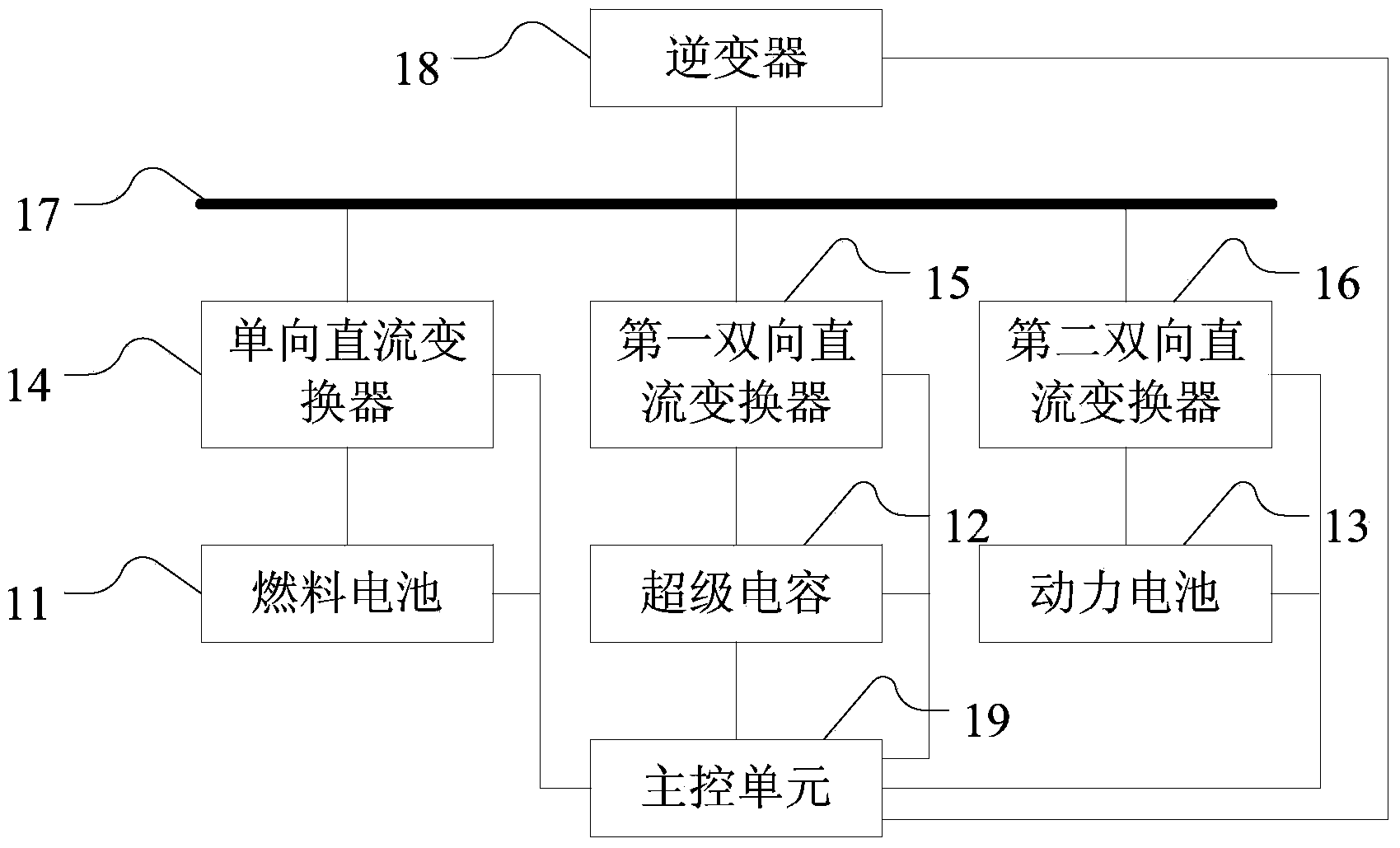
[0023] Such as figure 1 As shown, it is a schematic structural diagram of an embodiment of a tram power system provided by the present invention, which specifically includes: a fuel cell 11, a supercapacitor 12, a power battery 13, a unidirectional DC converter 14, a first bidirectional DC converter 15, a second A bidirectional DC converter 16, a DC bus 17, an inverter 18 and a main control unit 19; the fuel cell 11 is connected to the unidirectional DC converter 14; the supercapacitor 12 is connected to the first bidirectional DC converter 15; the power battery 13 is connected to the second bidirectional DC converter 16; the unidirectional DC converter 14, the first bidirectional DC converter 15, and the second bidirectional DC converter 16 pass through the The DC bus 17 is connected to the inverter 18; the inverter 18 is connected to the motor of the tram; the fuel cell 11, the supercapacitor 12, the power battery 13, the second A bidirectional DC converter 15, the second b...

Embodiment 2

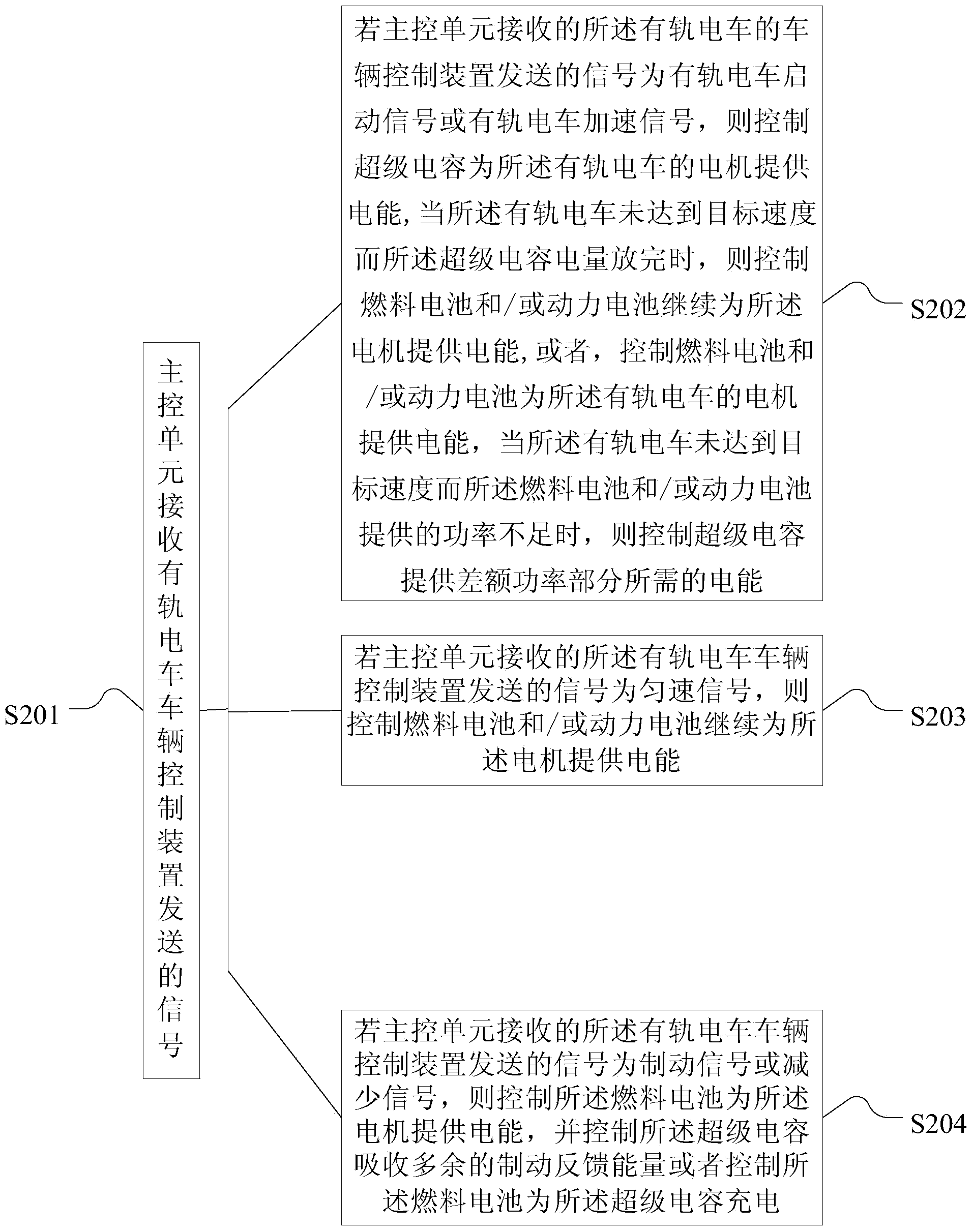
[0032] Such as figure 2 As shown, it is a schematic flow chart of an embodiment of a control method for a tram power system provided by the present invention, which specifically includes the following steps:

[0033] S201. The main control unit receives the signal sent by the tram vehicle control device;

[0034]The main control unit is connected to the tram vehicle control device through a network bus, such as CAN bus, MVB bus, etc., and is used to receive signals sent by the tram vehicle control device.

[0035] S202. If the signal sent by the tram vehicle control device received by the main control unit is a tram start signal or a tram acceleration signal, control the supercapacitor to provide electric energy for the motor of the tram, when the When the tram does not reach the target speed and the supercapacitor is discharged, the fuel cell and / or the power battery are controlled to continue to provide electric energy for the motor, or the fuel cell and / or the power batte...


PUM


Abstract

The invention discloses a tramcar power system and a control method. The system is characterized in that a fuel battery is connected with a unidirectional direct-current converter; a super capacitor is connected with a first bidirectional direct-current converter; a power battery is connected with a second bidirectional direct-current converter; the unidirectional direct-current converter, the first bidirectional direct-current converter and the second bidirectional direct-current converter are connected with an inverter by direct-current buses; the inverter is connected with a motor of a tramcar; the fuel battery, the super capacitor, the power battery, the first bidirectional direct-current converter, the second bidirectional direct-current converter and the inverter are connected with a main control unit; the main control unit is connected with a control device of the tramcar. According to the tramcar power system and the control method, the super capacitor, the fuel battery and the power battery are matched for supplying power so that the disadvantages that energy of the super capacitor is not enough and the power property of the power battery is not enough are solved, and the disadvantage complementation of energy-storing parts is realized; the fuel battery and the power battery are mutually redundant so as to realize the emergency rescuing under a fault condition of a power supplying part.

Description

technical field [0001] The invention relates to the technical field of hybrid power systems, in particular to a tram power system and a control method. Background technique [0002] In recent years, due to serious environmental pollution, depletion of oil resources and global warming, many cities in China have begun to plan and build trams, and set up off-grid areas in important sections to protect the urban landscape. At the same time as the high-speed rail transit and the popularization of urban rail transit, through the research on energy storage technology and intelligent control strategy, to achieve the goal of energy saving, environmental protection, safety and reliability of rail transit will become a symbol of the modernization of rail transit technology in the new century . [0003] At present, Tangche Company has developed a hybrid 100% low-floor tram that is jointly powered by catenary, on-board supercapacitors, and power batteries. The power supply strategy of ...

Claims


Application Information

Patent Timeline
IPC IPC(8): B61C3/00B61C17/00B60L11/18
CPCB61C3/02B61C7/04B60L50/40B60L58/30B60L58/40Y02T30/00Y02T90/40Y02T10/70B60L1/14B60L13/006B60L15/002B61C17/00B61D27/00B61D29/00
Inventor 孙帮成陈维荣黄烈威李明高李明刘志祥石俊杰臧晓燕
Owner CRRC TANGSHAN CO LTD
Why Eureka
Try Eureka