
Economizer for improving temperature of smoke in inlet of SCR system

A technology of SCR system and flue gas temperature, which is applied in the direction of feed water heaters, chemical instruments and methods, lighting and heating equipment, etc., can solve the problems of power plants that are difficult to meet environmental protection indicators, the service life of catalysts is reduced, and the demand is low, so as to improve The effects of continuous operation time, increased reaction temperature, and enhanced denitrification capacity

Inactive Publication Date: 2014-07-02
SOUTHEAST UNIV +1
View PDF7 Cites 2 Cited by
  • Summary
  • Abstract
  • Description
  • Claims
  • Application Information

AI Technical Summary

Problems solved by technology

However, power plant boilers cannot operate at high load for a long time. During the off-peak period of electricity consumption, the power grid’s demand for power generation load of the power plant is low, and the power plant boiler operates under low load. At this time, the reaction temperature of the flue gas in the SCR system is low. The activity decreases with the decrease of temperature, so the denitrification efficiency is also low
In addition, when the flue gas temperature at the inlet of the denitrification device does not reach the lower limit of the operating temperature of the denitrification system, the denitrification system will stop operating, and the emission of nitrogen oxides will increase, making it difficult for the power station to meet the environmental protection indicators stipulated by the state.
On the other hand, although the catalyst stops working, it is still being washed by the flue gas, and the wear of the catalyst by the fly ash does not decrease, resulting in a reduction in the service life of the catalyst

Method used


Image

  • Economizer for improving temperature of smoke in inlet of SCR system
  • Economizer for improving temperature of smoke in inlet of SCR system

Examples


Embodiment Construction

[0016] The present invention will be further described below in conjunction with the accompanying drawings.

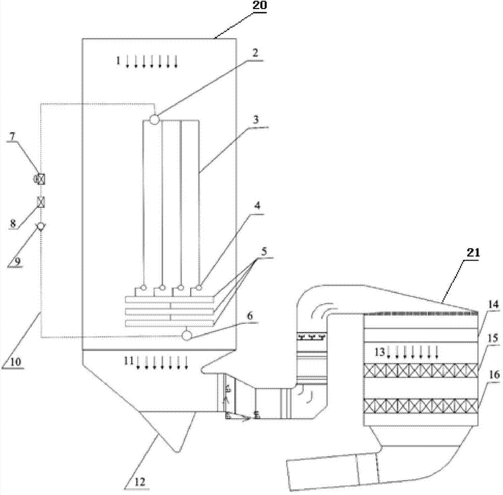
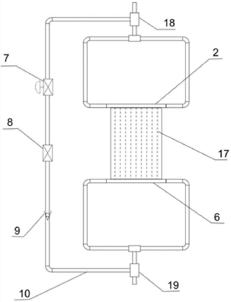
[0017] Such as figure 1 and figure 2 As shown, an economizer for improving the flue gas temperature at the inlet of the SCR system includes a housing 20, an economizer outlet header 2 arranged in the housing 20, and a group of economizer outlet headers 2 connected to the economizer Coaler suspension pipe 3, economizer intermediate header 4 connected to each economizer suspension pipe 3, a group of economizer serpentine pipes 5 connected to economizer intermediate header 4, and economizer The economizer inlet header 6 connected with the serpentine tube 5 of the economizer and the SCR reactor connected with the bottom of the shell 20; a branch pipe is arranged between the economizer inlet header 6 and the economizer outlet header 2 10. The branch pipe 10 is provided with a one-way valve 9, a shut-off valve 8 and a flow regulating valve 7 in sequence along the fluid fl...


PUM


Abstract

The invention discloses an economizer for improving the temperature of smoke in an inlet of an SCR system. A branch pipeline is arranged on a water supply pipeline connected with an inlet header of the economizer and connected with a lead-out pipe of an outlet header of the economizer. A one-way valve, a stop valve and a regulating valve are arranged on the branch pipeline. The temperature of smoke in an outlet of the economizer is increased by regulating the opening degree of the valves in the branch pipeline and reducing the amount of heat exchanged between the economizer and smoke under the low-load working condition, and rise of the temperature of the outlet of the economizer means that the reaction temperature of the SCR denitrification system is increased; on one hand, loads meet the requirement for conditions of SCR operation within a wider range, and continuous running time of the SCR denitrification system in a power plant is prolonged; on the other hand, the activity of SCR catalysts is improved under the low-load working condition, the denitrification capacity of the SCR system is enhanced, and the economizer assists the power plant in better reaching the environmental index within the wider time range.

Description

technical field [0001] The invention relates to the field of flue gas denitrification of power station boilers, in particular to an economizer for increasing the temperature of flue gas at the inlet of an SCR system. Background technique [0002] In the fields of ships, motor vehicles and thermal power plants, the combustion of engines or boilers can produce nitrogen oxides NO x , NO x by NO, NO 2 and N 2 O composition is one of the important sources of environmental pollution. The discharge of these polluting gases into the atmosphere will cause acid rain, photochemical smog, ozone layer depletion and other hazards, affecting human life. SCR technology is that under the action of a catalyst, the reactants are adsorbed on the catalyst to generate N that is harmless to humans. 2 and H 2 0, due to the presence of catalysts, the denitrification efficiency can reach a very high level, and selective catalytic reduction (SCR) has become the most important denitrification tec...

Claims


Application Information

Patent Timeline
IPC IPC(8): F22D1/00F23J15/02B01D53/90B01D53/56
Inventor 喻聪司风琪桂汉生
Owner SOUTHEAST UNIV
Learn More