All-fiber cascade laser amplification method and device with polarization controlled automatically and stably
An automatic stabilization and laser amplification technology, applied in the laser field, can solve problems such as immature manufacturing process, difficulty in making double-clad gain fiber, and restrictions on popularization and application, so as to maintain good pulse time spectrum waveform and reduce high-order nonlinearity Optical effects, effects with many adjustable parameters
- Summary
- Abstract
- Description
- Claims
- Application Information
AI Technical Summary
Problems solved by technology
Method used
Image
Examples
Embodiment 1
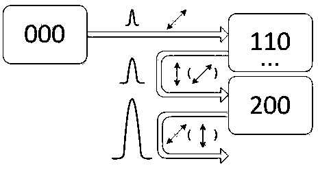
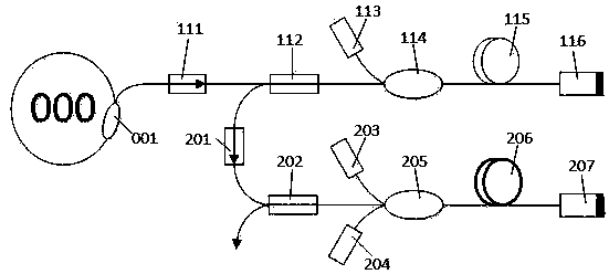
[0033] refer to figure 2, is a schematic diagram of the device of the present invention based on a one-stage forward pre-amplification structure, which includes a seed source 000, a one-stage pre-amplification structure 110 based on a Faraday rotating mirror, and a main amplification structure 200 based on a Faraday rotating mirror. The seed source 000 can be a Q-switched pulse laser or a mode-locked pulse laser. The primary pre-amplification structure 110 includes: a polarization maintaining fiber isolator 111, a polarization beam splitter 112, a semiconductor laser 113, a wavelength division multiplexer 114, Erbium-doped gain fiber 115 and Faraday rotating mirror 116 . The common end of the polarization beam splitter 112 is an ordinary non-polarization-maintaining single-mode optical fiber, the preferred wavelength of the semiconductor laser 113 is 976nm, the preferred single-mode optical fiber of the erbium-doped gain fiber 115, and the Faraday rotator 116 has a wavelength...
Embodiment 2
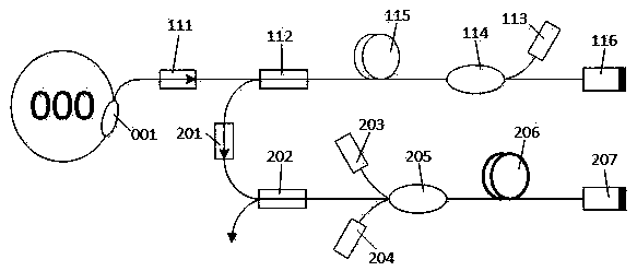
[0036] refer to image 3 , is a schematic diagram of the device of the present invention based on a one-stage inverse pre-amplification structure, which includes a seed source 000, a one-stage pre-amplification structure 110 based on a Faraday rotating mirror, and a main amplification structure 200 based on a Faraday rotating mirror. The seed source 000 can be a Q-switched pulse laser or a mode-locked pulse laser. The primary pre-amplification structure 110 includes: a polarization maintaining fiber isolator 111, a polarization beam splitter 112, a semiconductor laser 113, a wavelength division multiplexer 114, Erbium-doped gain fiber 115 and Faraday rotating mirror 116 . The common end of the polarization beam splitter 112 is an ordinary non-polarization-maintaining single-mode fiber, the preferred wavelength of the semiconductor laser 113 is 976nm, the preferred gain fiber 115 is an erbium-doped ion single-mode fiber, and the Faraday rotator 116 has a wavelength greater than...
Embodiment 3
[0039] refer to Figure 4 , is a schematic diagram of the device of the present invention based on the secondary forward pre-amplification structure, which includes the seed source 000, the secondary pre-amplification structures 110, 120 based on the Faraday rotating mirror and the main amplification structure 200 based on the Faraday rotating mirror. The seed source 000 can be a Q-switched pulse laser or a mode-locked pulse laser. The secondary pre-amplification structures 110 and 120 include: polarization-maintaining fiber isolators 111 and 121, polarization beam splitters 112 and 122, and semiconductor lasers 113 and 123 , wavelength division multiplexers 114, 124, erbium-doped gain fibers 115, 125 and Faraday rotating mirrors 116, 126. The common end of polarization beam splitter 112, 122 is common non-polarization-maintaining single-mode fiber, semiconductor laser 113, 123 operating wavelength is preferably 976nm, gain fiber 115, 125 is preferably erbium-doped single-mode...
PUM
 Abstract
Description
Claims
Application Information
 - R&D
- Intellectual Property
- Life Sciences
- Materials
- Tech Scout
- Unparalleled Data Quality
- Higher Quality Content
- 60% Fewer Hallucinations
Browse by: Latest US Patents, China's latest patents, Technical Efficacy Thesaurus, Application Domain, Technology Topic, Popular Technical Reports.
© 2025 PatSnap. All rights reserved.Legal|Privacy policy|Modern Slavery Act Transparency Statement|Sitemap|About US| Contact US: help@patsnap.com


