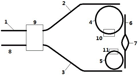
Reflective cavity-mirror structure for high-speed q-modulated, wavelength-tunable waveguide lasers
A laser and tuning wave technology, applied in the field of reflective cavity mirror structure, can solve the problems of complex fabrication, inability to increase the modulation bandwidth, and inability to achieve, and achieve the effect of simple process
- Summary
- Abstract
- Description
- Claims
- Application Information
AI Technical Summary
Problems solved by technology
Method used
Image
Examples
Embodiment 1
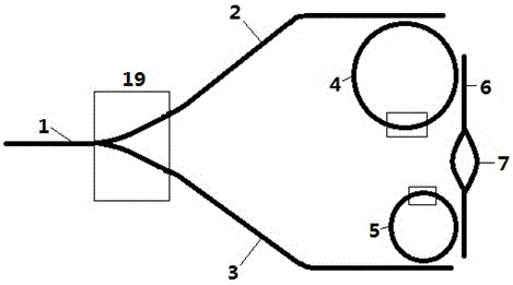
[0023] Such as figure 2 As shown, the device is made of silicon-on-insulator (SOI) material, the thickness of the top silicon layer is 220 nm, and the thickness of the silicon dioxide buried layer is 1 μm. Using CMOS technology, through deep ultraviolet lithography and silicon dry etching, a ridge-shaped optical waveguide with a width of 400nm and a depth of 180nm is produced. After the silicon dry etching is completed, the chemical vapor deposition method is used to cover 2μm Silicon layer, composed of figure 2 The basic device structure shown.
[0024] A symmetrical Y branch structure 19 is used in the device as a beam splitting coupling structure. The two optical microrings in the device have radii of 5 μm and 7 μm, respectively. The gap between the optical microring and the two parallel waveguides is 180 nm. The tuning of the optical microring utilizes the thermo-optic effect of silicon to fabricate a heating electrode corresponding to the microring on the silicon di...
Embodiment 2
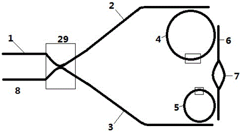
[0027] Such as image 3 As shown, the device is made of silicon-on-insulator (SOI) material, the thickness of the top silicon layer is 220 nm, and the thickness of the silicon dioxide buried layer is 1 μm. Using CMOS technology, through deep ultraviolet lithography and silicon dry etching, a ridge-shaped optical waveguide with a width of 400nm and a depth of 180nm is produced. After the silicon dry etching is completed, the chemical vapor deposition method is used to cover 2μm Silicon layer, composed of image 3 The basic device structure shown.
[0028] The X cross junction structure 29 is used as the beam splitting coupling structure in the device. The two optical microrings in the device have radii of 5 μm and 5 μm, respectively. The gap between the optical microring and the two parallel waveguides is 180 nm. The tuning of the optical microring utilizes the thermo-optic effect of silicon to fabricate a heating electrode corresponding to the microring on the silicon diox...
Embodiment 3
[0031] Such as Figure 4 As shown, the device is made of silicon-on-insulator (SOI) material, the thickness of the top silicon layer is 220 nm, and the thickness of the silicon dioxide buried layer is 1 μm. Using CMOS technology, through deep ultraviolet lithography and silicon dry etching, a ridge-shaped optical waveguide with a width of 400nm and a depth of 180nm is produced. After the silicon dry etching is completed, the chemical vapor deposition method is used to cover 2μm Silicon layer, composed of Figure 4 The basic device structure shown.
[0032] A directional coupler 39 is used as a beam splitting coupling structure in the device. The two optical microrings in the device have radii of 7 μm and 7 μm, respectively. The gap between the optical microring and the two parallel waveguides is 180 nm. The tuning of the optical microring utilizes the thermo-optic effect of silicon to fabricate a heating electrode corresponding to the microring on the silicon dioxide layer...
PUM
 Abstract
Description
Claims
Application Information
 - R&D
- Intellectual Property
- Life Sciences
- Materials
- Tech Scout
- Unparalleled Data Quality
- Higher Quality Content
- 60% Fewer Hallucinations
Browse by: Latest US Patents, China's latest patents, Technical Efficacy Thesaurus, Application Domain, Technology Topic, Popular Technical Reports.
© 2025 PatSnap. All rights reserved.Legal|Privacy policy|Modern Slavery Act Transparency Statement|Sitemap|About US| Contact US: help@patsnap.com


