A methanation fluidized bed reactor
A fluidized bed reactor and methanation technology, applied in chemical instruments and methods, chemical/physical processes, petroleum industry, etc., can solve problems such as poor safety and reliability, high reaction temperature, increased product concentration, etc., reaching the number of equipment The effect of less, low reaction temperature, and reduced consumption
- Summary
- Abstract
- Description
- Claims
- Application Information
AI Technical Summary
Problems solved by technology
Method used
Image
Examples
Embodiment 1
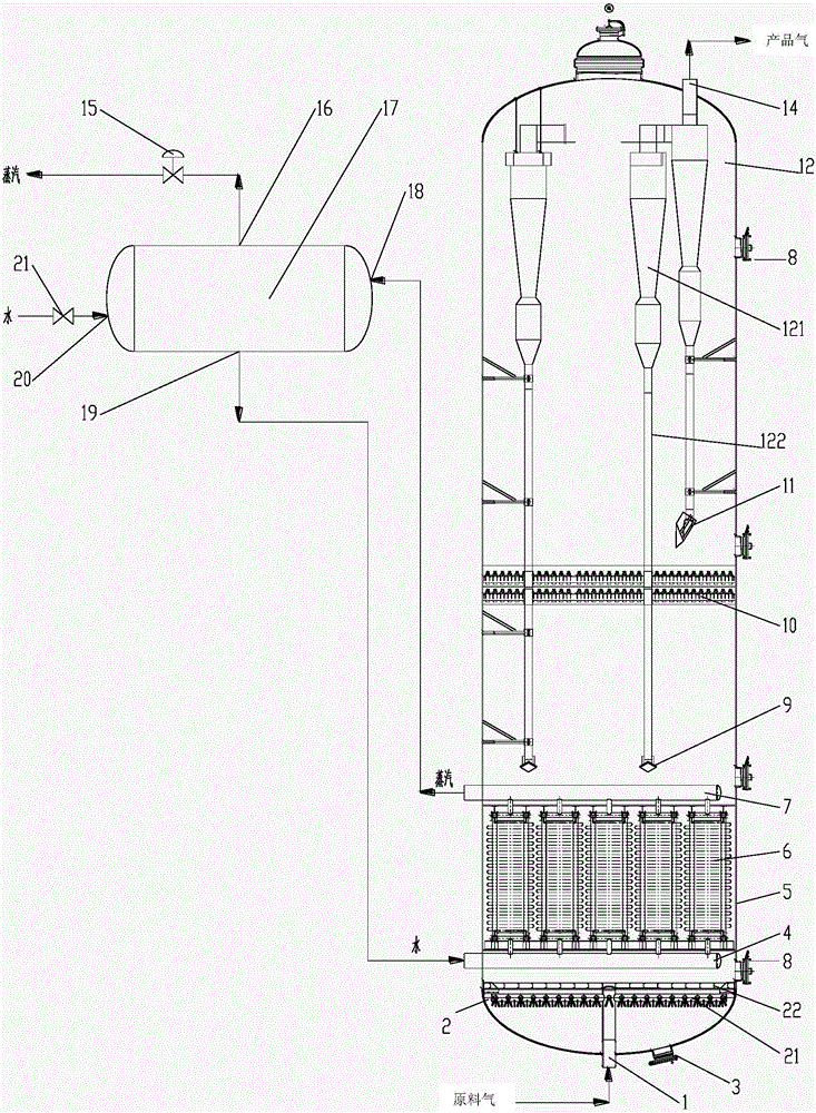
[0079] Such asfigure 1 As shown, the fluidized bed reactor includes a vertical cylindrical shell 5 with both upper and lower ends of the head, the lower head of the cylindrical shell 5 is provided with a feed gas inlet 1, and the upper head of the shell 5 is A product gas outlet 14 is installed, and a gas distributor 2 is provided near the bottom of the inner space of the housing. The gas distributor 2 includes a primary gas distributor 21 and a secondary gas distributor 22. The primary gas distributor 21 includes multiple nozzles on substantially the same horizontal plane; the secondary gas distributor 22 is a plate with a plurality of openings, located above the primary gas distributor 21 . The plane in which the gas distributor 2 is located is substantially perpendicular to the longitudinal axis of the reactor.
[0080] The primary gas distributor 21 is directly connected with the feed gas inlet 1 through a pipeline. The gas input from the raw gas inlet is evenly distribut...
Embodiment 2
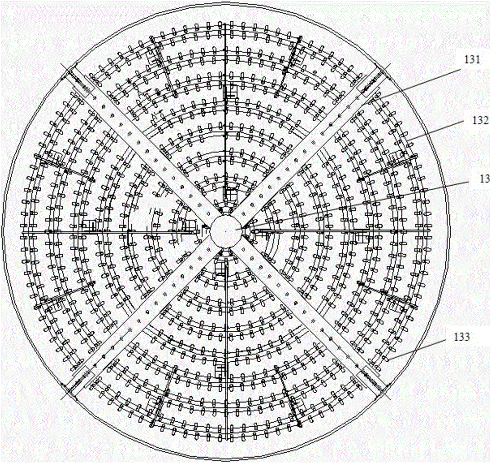
[0086] Such as figure 2 shown. The primary gas distributor 21 includes a plurality of annular pipes 132 distributed on the same plane, and the annular pipes are connected through radial branch pipes 131, and each radial branch pipe 131 is collected in the central pipe 13, and the central pipe 13 is the communication source gas Inlet piping with primary gas distributor. The nozzles 133 are connected to the annular pipe 132 and distributed with the ground.
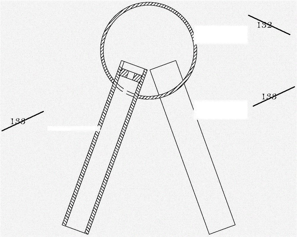
[0087] image 3 An enlarged view of the nozzle is shown. The nozzle 133 is connected to the annular pipe 132, and the opening of the nozzle 133 is downward; preferably, the nozzle includes a spray hole (only shown in the left nozzle, not shown in the right nozzle) and an extended pipeline located outside the spray hole, in a certain shape. Angled (eg, about 30°) toward the bottom of the reactor, the pipe walls between adjacent nozzles 133 are angled in opposite directions.
Embodiment 3
[0089] The preferred gas trap 10 includes a two-layer structure. Figure 4A A schematic diagram showing a preferred solution of a single-layer structure, in the same plane, consisting of protrusions arranged in different directions in the middle and on both sides. Figure 4B A magnified view of the protrusion arrangement is shown. Each bump is actually a claw-like intersection structure, such as Figure 4C shown.
[0090] The arrangement directions of the upper and lower two-layer structures are staggered at 90° (not shown in the figure).
PUM
| Property | Measurement | Unit |
|---|---|---|
| particle size | aaaaa | aaaaa |
| separation | aaaaa | aaaaa |
| separation | aaaaa | aaaaa |
Abstract
Description
Claims
Application Information
 - R&D
- Intellectual Property
- Life Sciences
- Materials
- Tech Scout
- Unparalleled Data Quality
- Higher Quality Content
- 60% Fewer Hallucinations
Browse by: Latest US Patents, China's latest patents, Technical Efficacy Thesaurus, Application Domain, Technology Topic, Popular Technical Reports.
© 2025 PatSnap. All rights reserved.Legal|Privacy policy|Modern Slavery Act Transparency Statement|Sitemap|About US| Contact US: help@patsnap.com


